FBX method for Video Mapping
Import a 3D model of the projection surface and set up Smode for Video Mapping.
If you want to video project on a complex surface that is not easy to reproduce in Smode, you may want to import a 3D model of that surface directly into Smode.
Import a FBX model
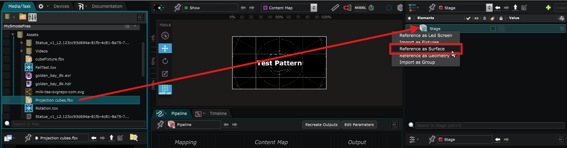
Drag and drop a
 3D File
from the media directories to the
3D File
from the media directories to the
 Stage
and select Reference as Surface.
Stage
and select Reference as Surface.
To learn more about the limitations, refer to the
3D File
documentation.
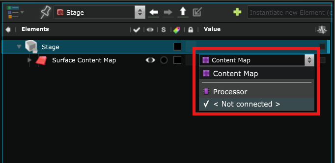
Select a Source for the content to display on that
 Surface
:
Surface
:
UV Mapping
How the content is projected onto the Surface depends on its UV map.
If you look at the
 Content Map
in your
Content Map
in your
 Viewport
, you will see the UV map of this Surface object directly in the
Content Map
.
Viewport
, you will see the UV map of this Surface object directly in the
Content Map
.
If this is not the way you want your content to be displayed, you can adapt the UV map to the content by using UV Modifier directly in the
Surface
in the
Stage
.
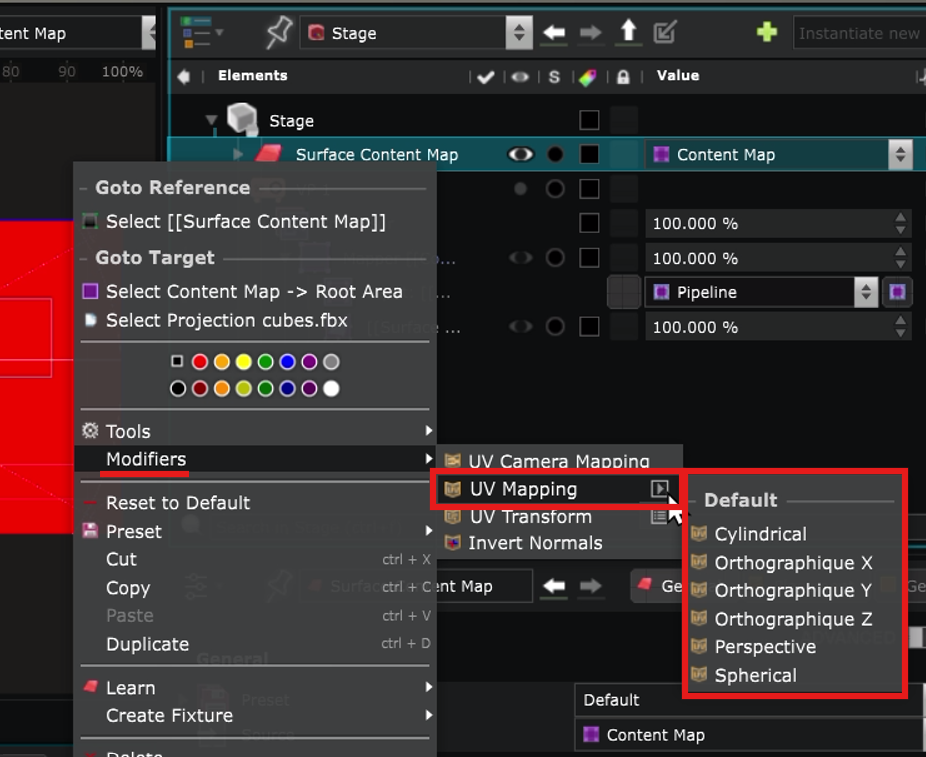
There are 3 types of UV Modifiers:
-
 UV Mapping
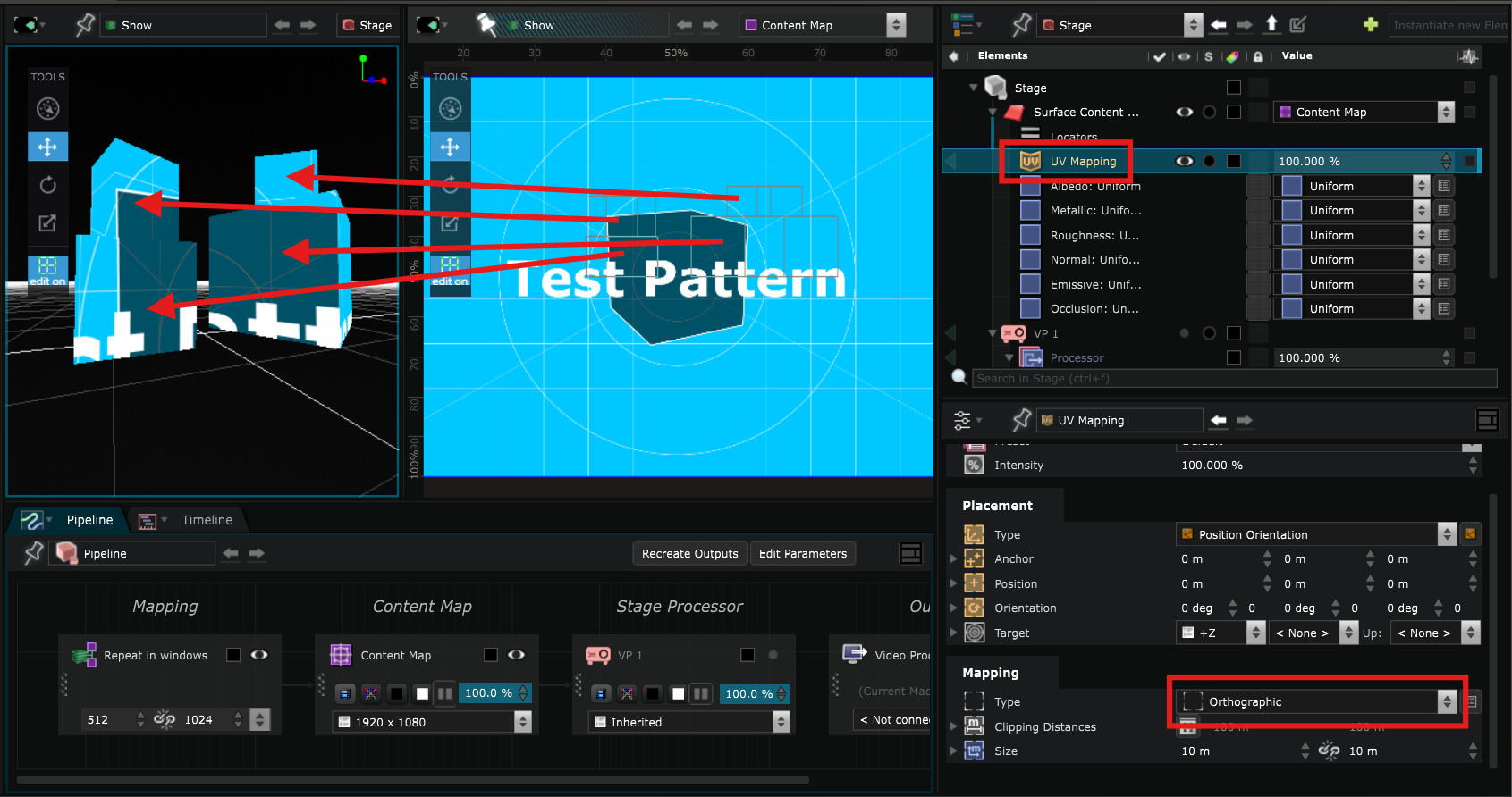
: can do a simple remapping such as Perspective, Orthographic, Cylindrical or Spherical:
UV Mapping
: can do a simple remapping such as Perspective, Orthographic, Cylindrical or Spherical:
For example, this is what Orthographic would look like:
-
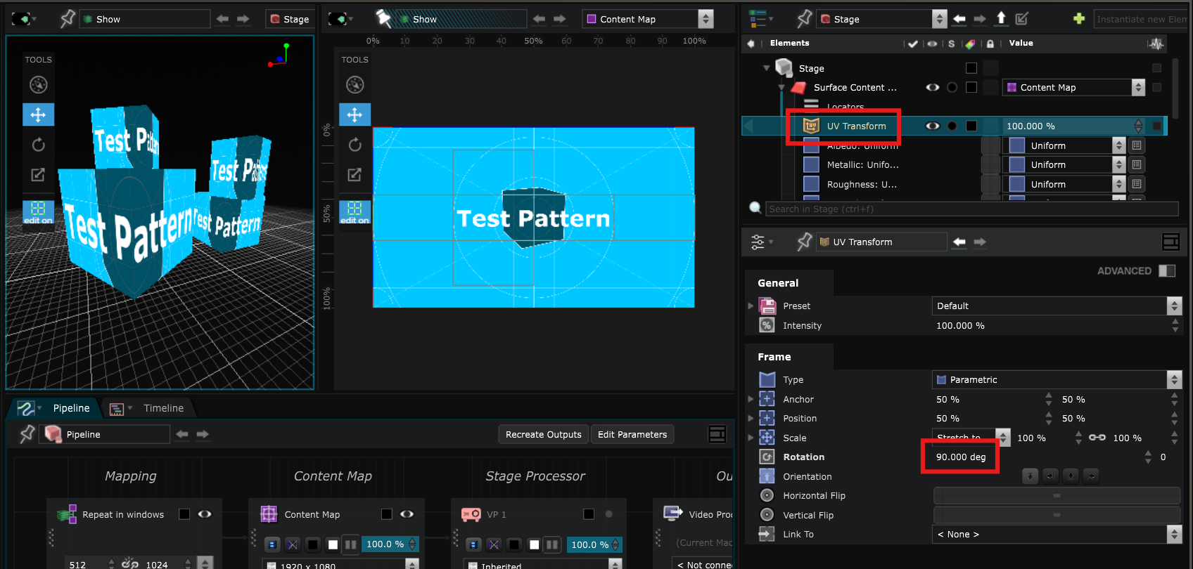
 UV Transform
: works exactly like a
UV Transform
: works exactly like a
 2D Transform
modifier but for the UV map of an object, such as translation, scale and rotation.
2D Transform
modifier but for the UV map of an object, such as translation, scale and rotation.
For example, you can rotate the content 90 degrees like that :
-
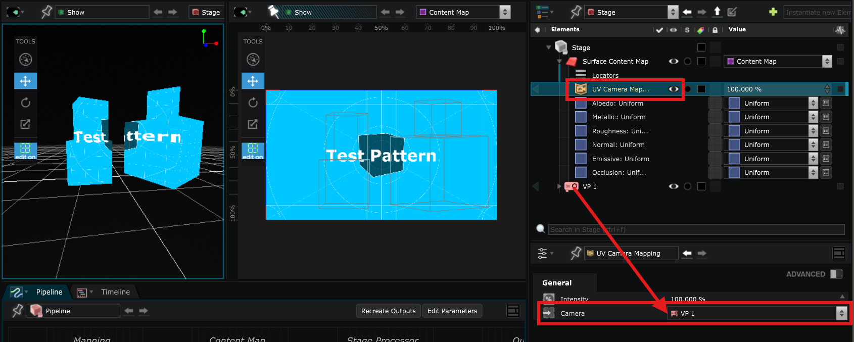
 UV Camera Mapping
: which will remap the UV of a mesh according to the point of view of a virtual
UV Camera Mapping
: which will remap the UV of a mesh according to the point of view of a virtual
 Camera
or
Camera
or
 Video Projector
.
Video Projector
.
This allows you to have the most coherent UV map according to the location from which you will see the projection without having to do everything by hand in another 3D modelling software.
Create a
Video Projector
in the
Stage
Virtual
Video Projector
of SMODE’s
Stage
are used for real life mapping and usually directly connected to the
 Video Output
.
Video Output
.
Right click in the
Stage
section of the
 Element Tree
to create one :
Element Tree
to create one :
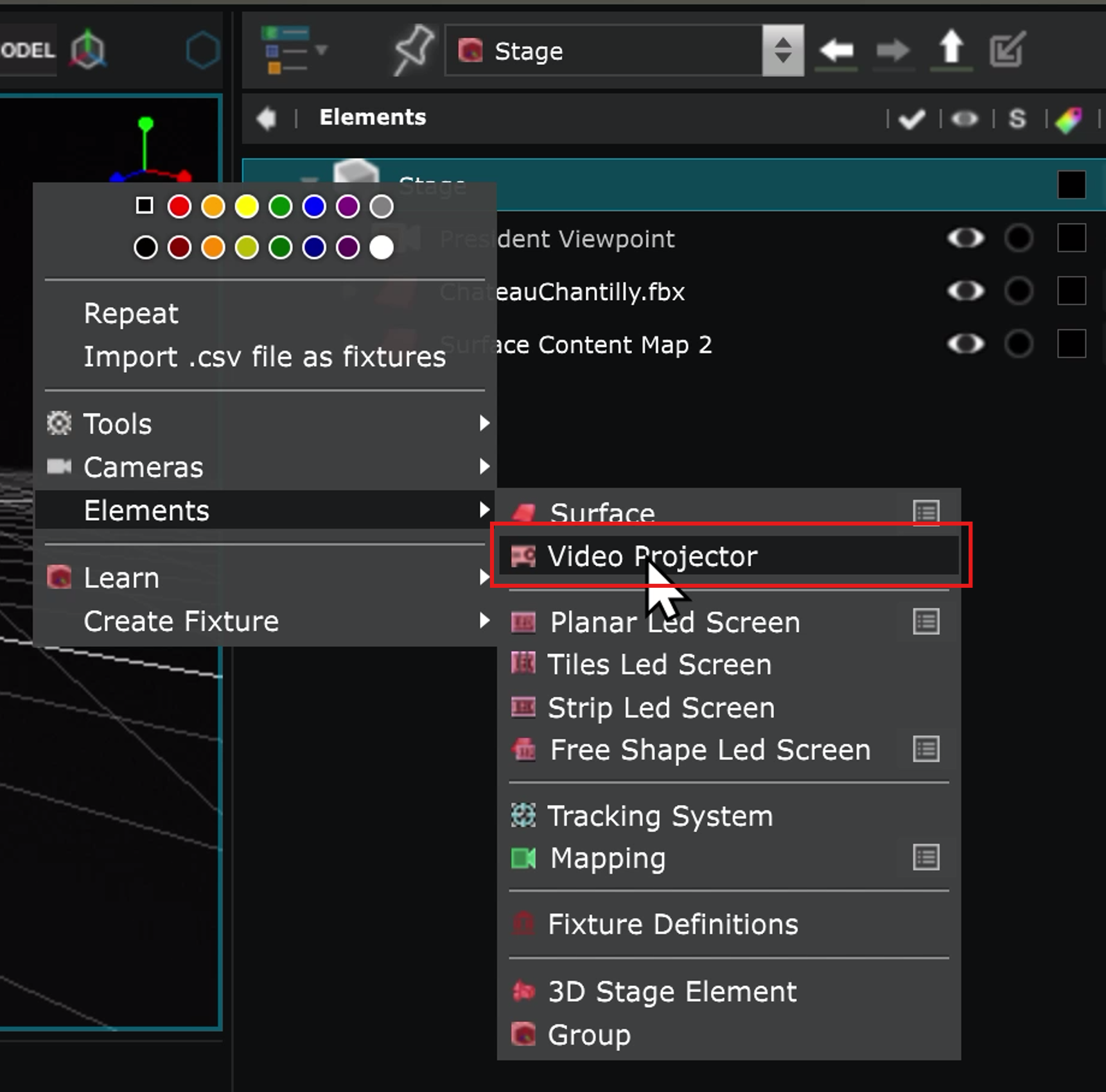
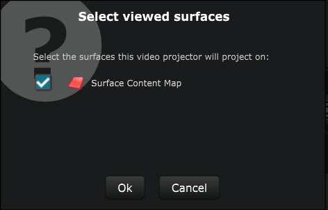
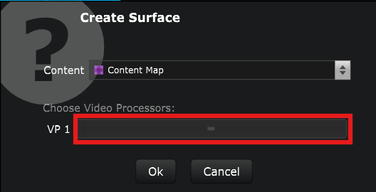
When you create a new
Video Projector
, you have to choose which
Surface
you want it to project on:
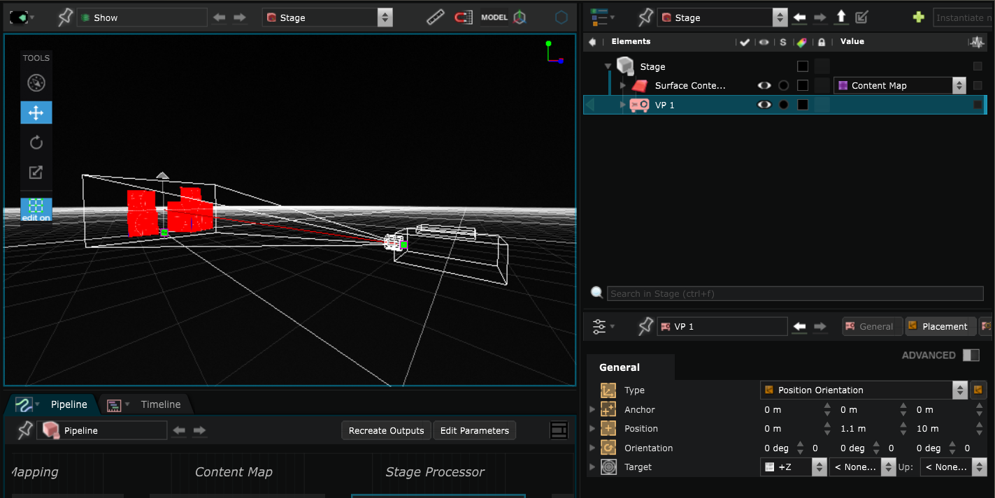
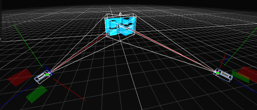
Place it where your real Video Projector is in the real world:
Understand the
 Mapper Generator
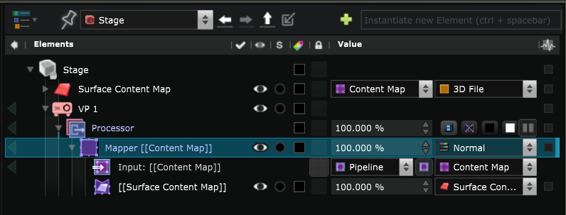
Because, even with the most detailed 3D model, the stage simulation will never completely fit to reality, you often need to adapt the projection. That’s what the
Mapper Generator
lets you do.
It is automatically created in the
 Processor
of the
Video Projector
with the content that will be projected as Input and the
Processor
of the
Video Projector
with the content that will be projected as Input and the
 Surface Mapper Item
on which it will be projected :
Surface Mapper Item
on which it will be projected :
Note that if you create a new
Surface
but do not select the
Video Projector
:
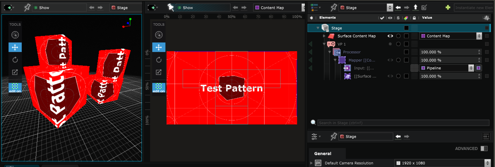
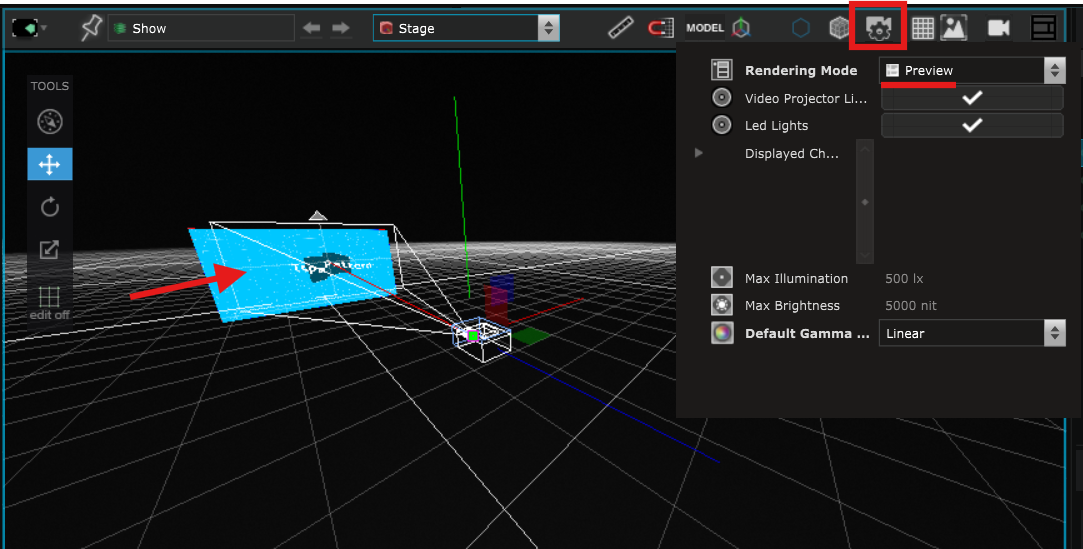
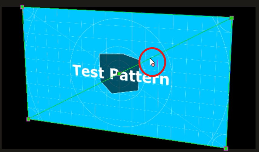
When the
Stage rendering options
is set to Preview, you can see the content displayed on the new
Surface
that you just created:
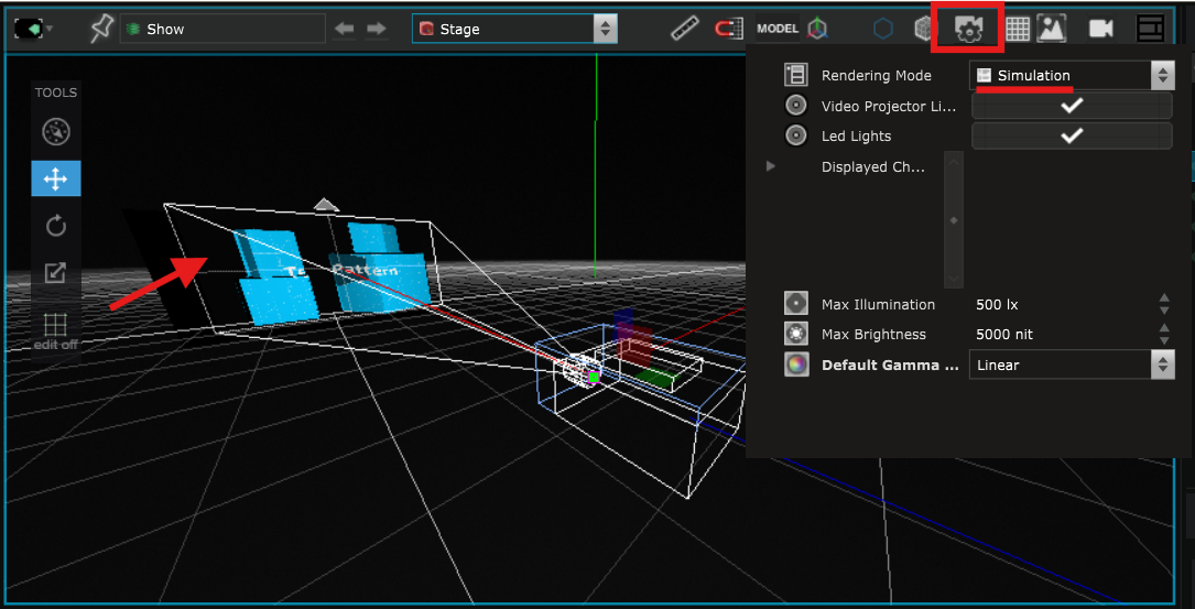
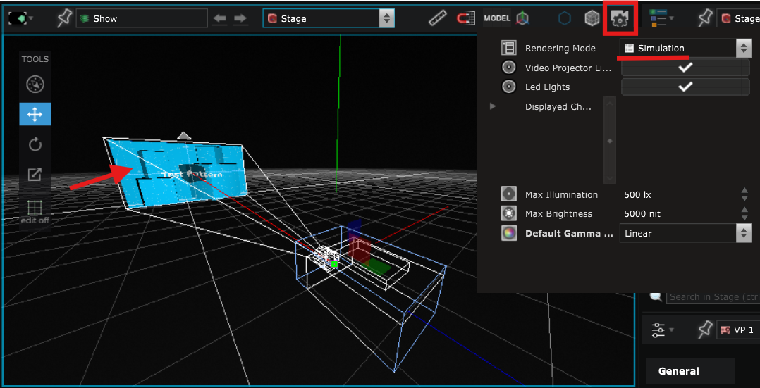
But if you set the
Stage rendering options
to Simulation, you see that the
Surface
is ignored by the
Video Projector
and the content is only displayed on the imported
Surface
:
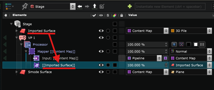
The reason is that there is a
Surface Mapper Item
for the imported
Surface
in the
Mapper Generator
of the
Video Projector
,
but there is no
Surface Mapper Item
for the new Smode
Surface
.
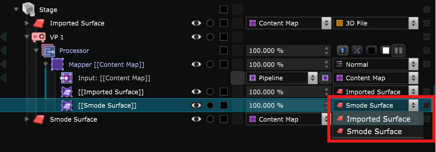
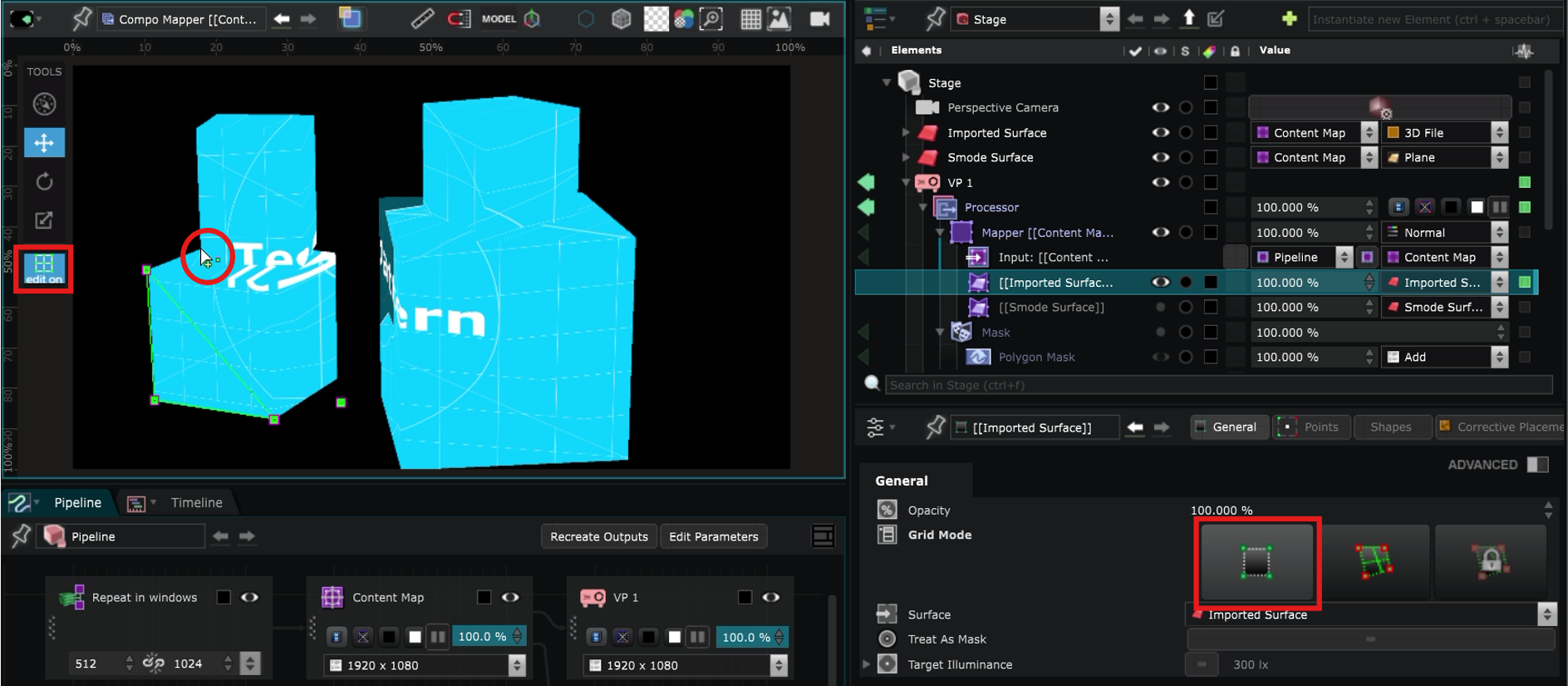
In order for the
Video Projector
to project on the Smode
Surface
, you need to create a new
Surface Mapper Item
for it.
To do so, you can right click on the
Mapper Generator
and create a new Surface.
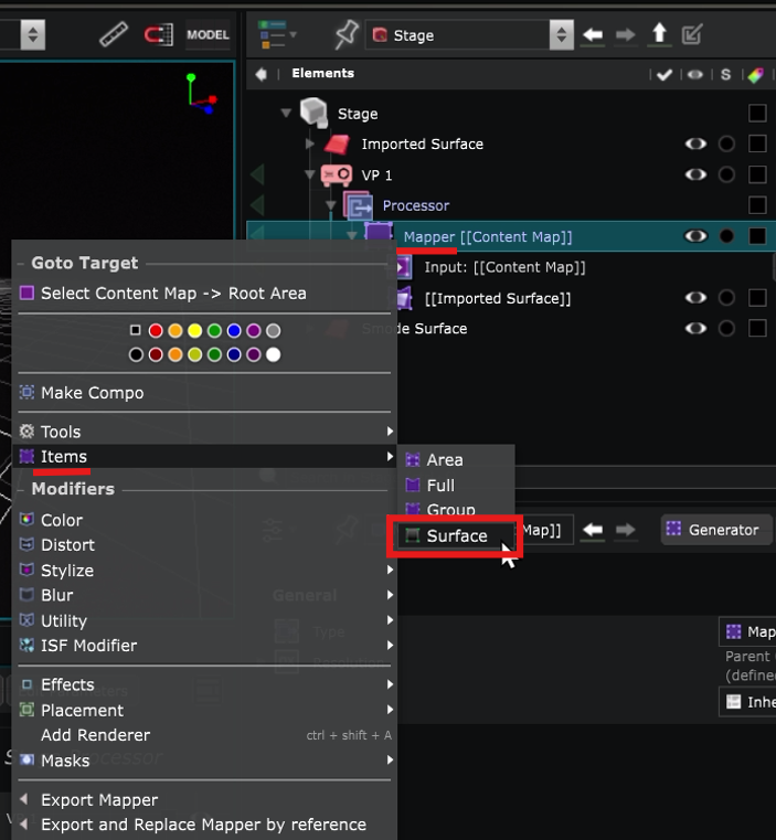
Select the Smode
Surface
in the list :
Now you can see that even when the
Stage rendering options
is set to Simulation, the content is projected to the Smode
Surface
as well.
Overlap
With the Simulation Stage rendering options , you can see that some areas are in the shade of other objects :
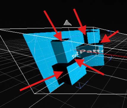
In this situation, you might want to add at least one other
Video Projector
to cover more angles of projection.
In the same way as for the first, create it in the
Element Tree
, select the
Surface
to project on and place them as you want in the 3D space:
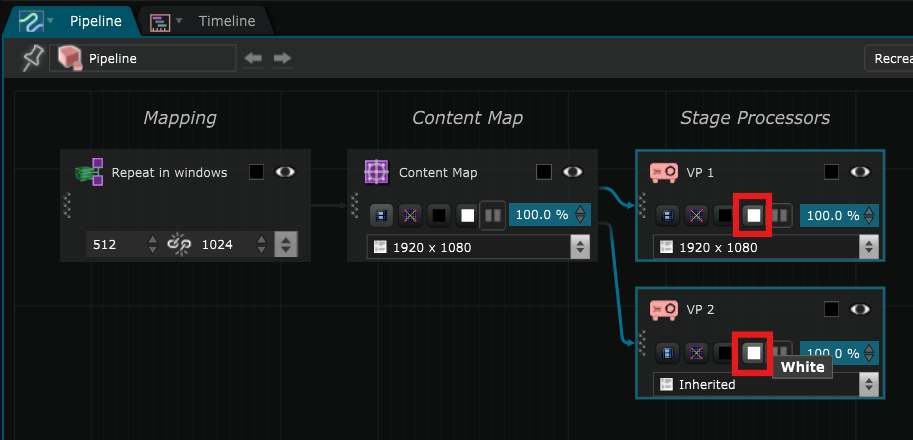
You can set both
Video Projector
to white mode directly in the
 Pipeline Editor
:
Pipeline Editor
:
This allows you to see the areas with more or less light and see if it is homogeneous or not:
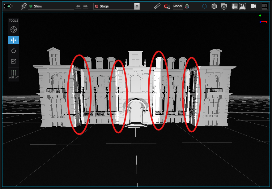
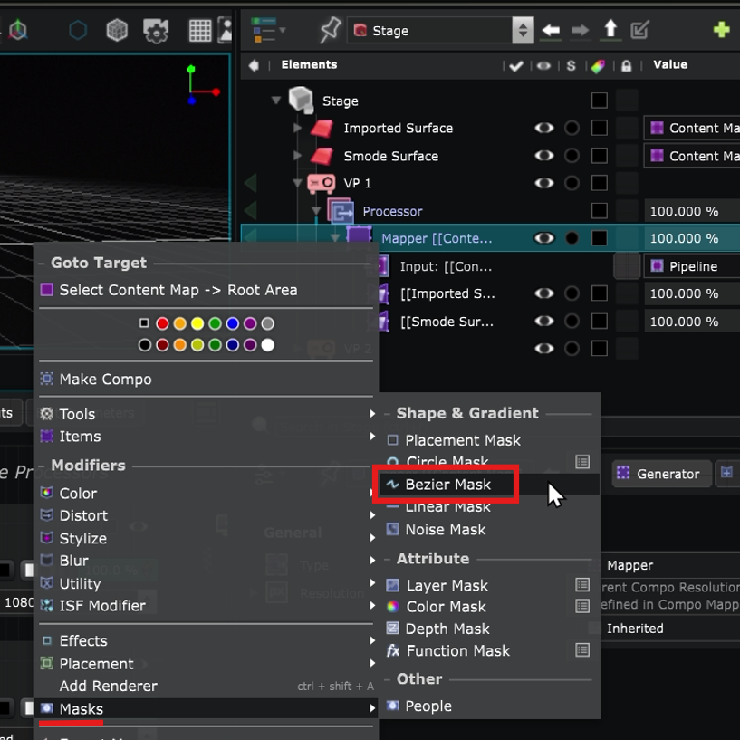
The goal is to mask the overlapping areas to have an homogeneous result. To to so, create a Bezier Mask in the
Mapper Generator
of the
Video Projector
:
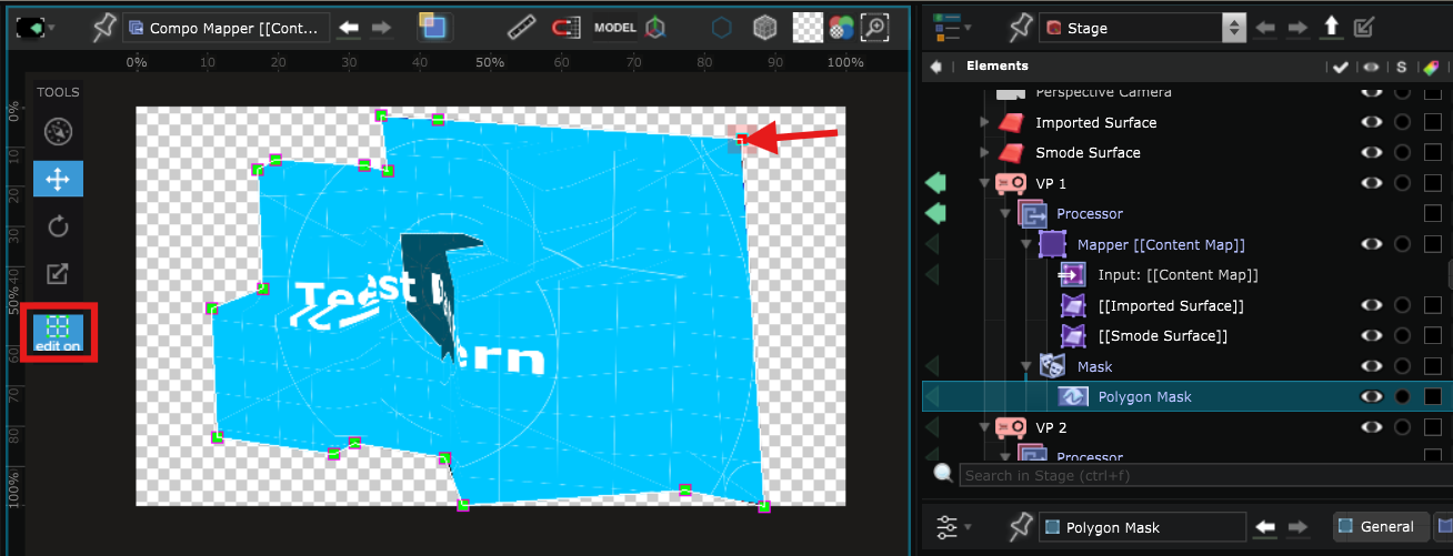
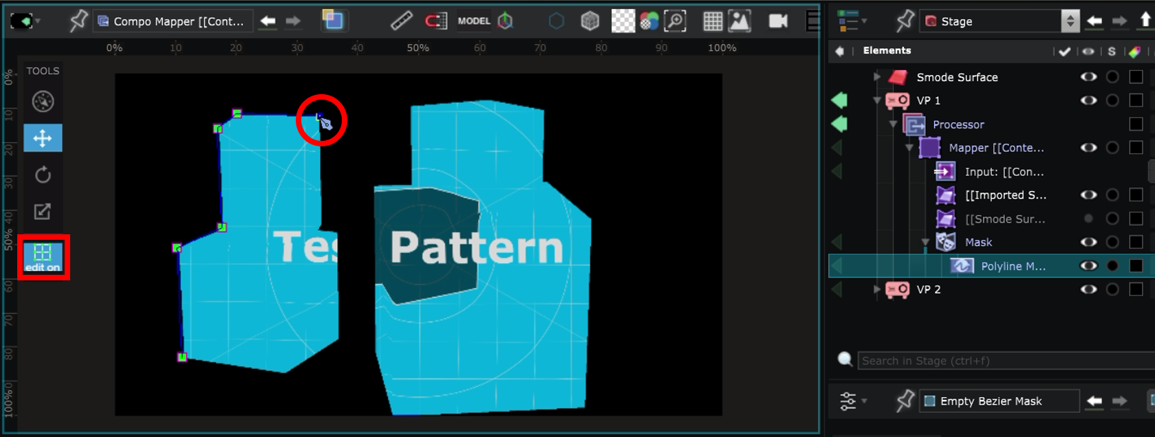
With the Bezier Mask selected, activate Edit On and create new points by pressing Ctrl and clicking in the
Viewport
:
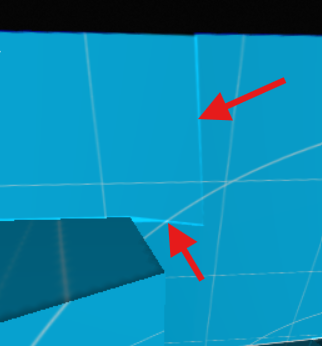
In the end, the result should look more homogeneous.
The edges can look a little too sharp:
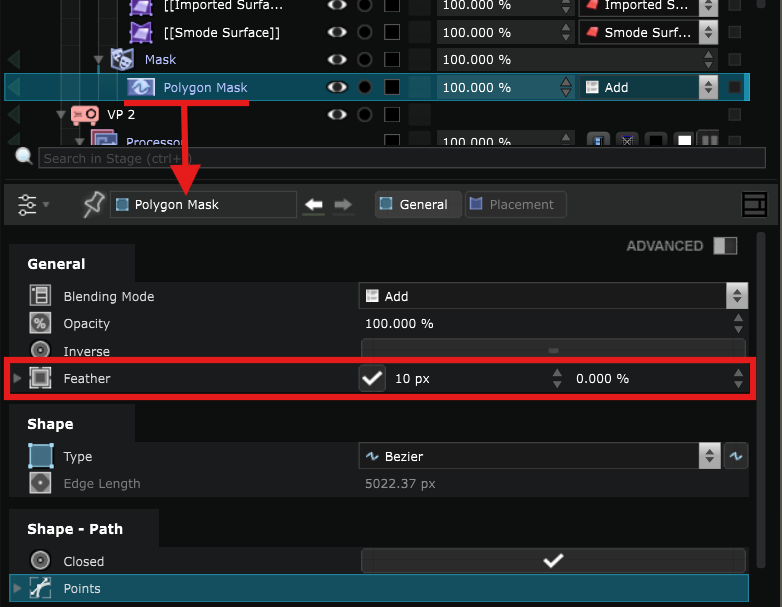
It is possible to smooth the edges by adding feather on the Masks:
Map the Content
For each
Video Projector
, after connecting it to the Smode server, you need to create a
Video Output Device
.
Refer to
Video Projector Device for Video Mapping
for more information.
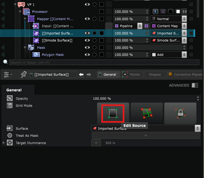
- In the
Surface Mapper Item
click on Edit Source Grid Mode. It allows you to create the point grid that you will use later to adjust the perspective:
Switch to Edit On, maintain Ctrl and click in the
Viewport
to create the point grid that you will use later to adjust the perspective :
Note: it is recommended to temporarily deactivate the Mask during this step.
By default the created shape is divided into triangles but you can also create segments between the points by pressing Ctrl when your cursor is inside a shape. You are also able to create segments between points.
Remove the points or segment by maintaining Shift and click.
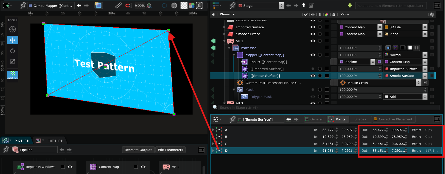
- Then, click on the Edit Target mode :
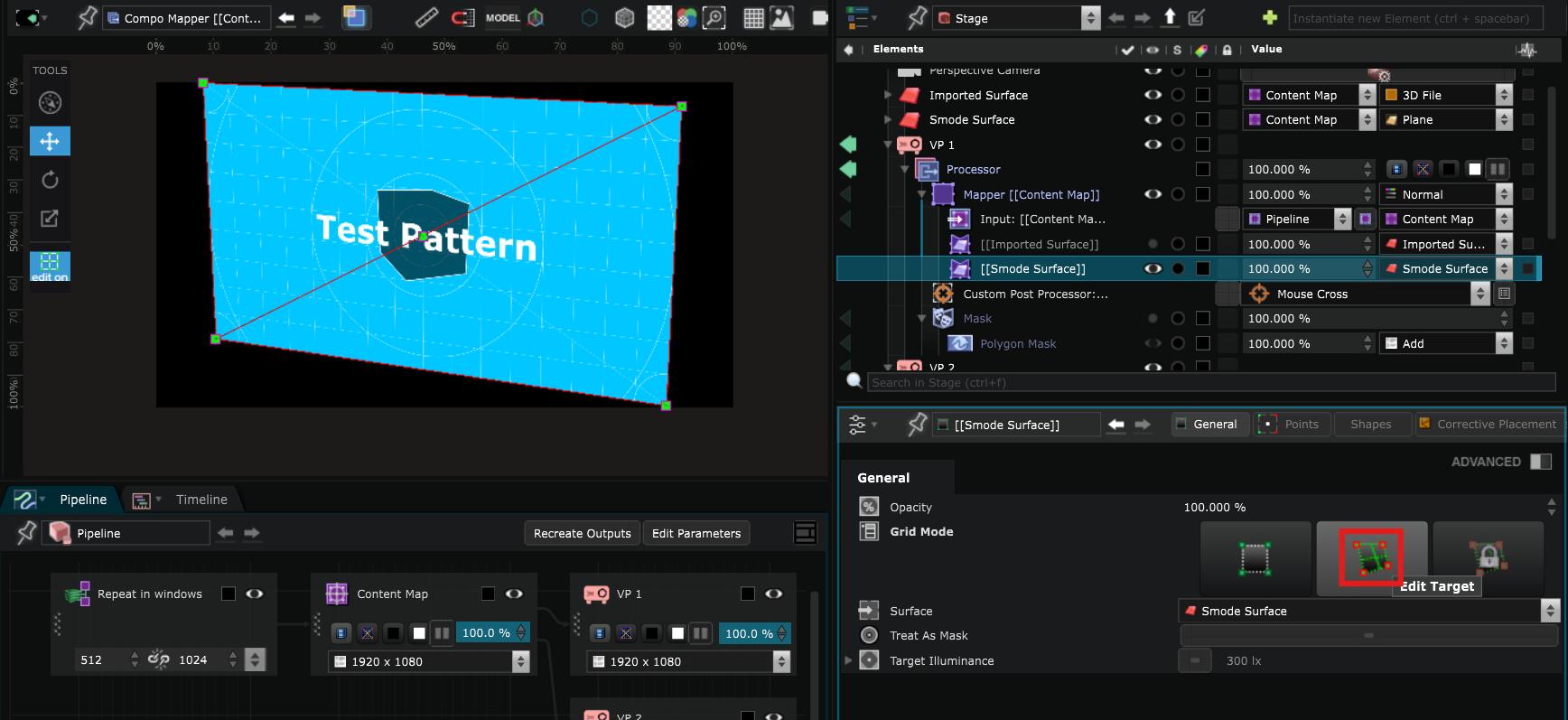
It will allow you to distort the image according to the grid of points that you have previously created :
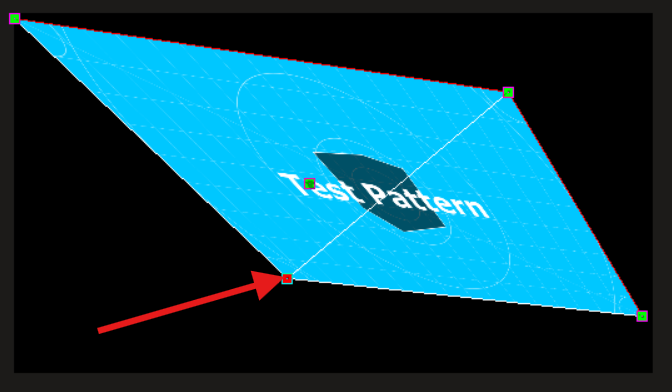
To edit more precisely, you can change the values of the points in the parameters by clicking and sliding up and down.
If you hold Shift while sliding, the values will change more slowly which allows you to be even more precise, and Ctrl+Shift to have the slowest movement possible :
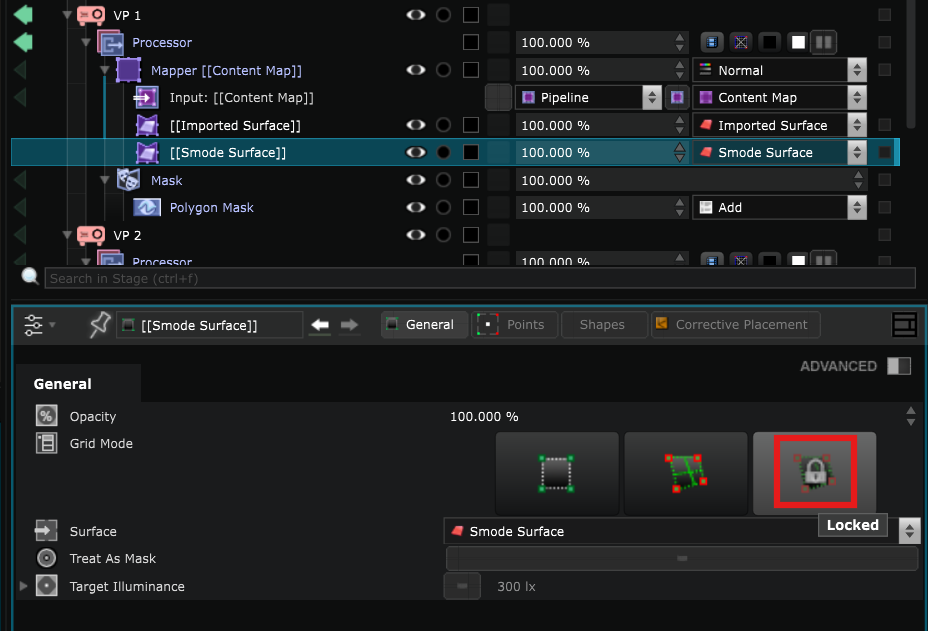
- For more safety, lock your warping with the Lock button:
Since you changed the shape a little, when you reactivate the Bezier Mask, you might need to make some adjustments :
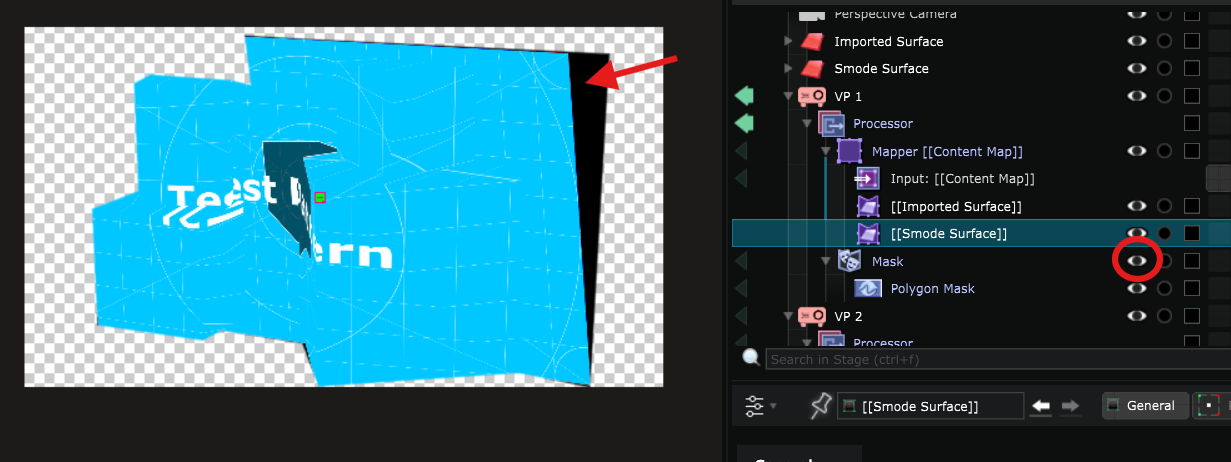
To do so, select the Bezier Mask and with Edit On use the helpers in the
Viewport
to move the points: