XR - Color Calibration
Blend perfectly the walls colors with the virtual surrounding.
XR - color calibration needs a specific XR/AR license.
If you’d like to try out these features to decide whether you want to purchase an XR/AR license, please contact us.
1 - Theory
Objectives:
In order to do
XR - Extended and augmented reality
, the colors of the video-input must be as close as possible to the colors of the overlay image.
However, between the screens and the camera, the image passes through several colorimetric profiles.
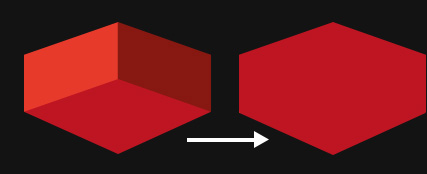
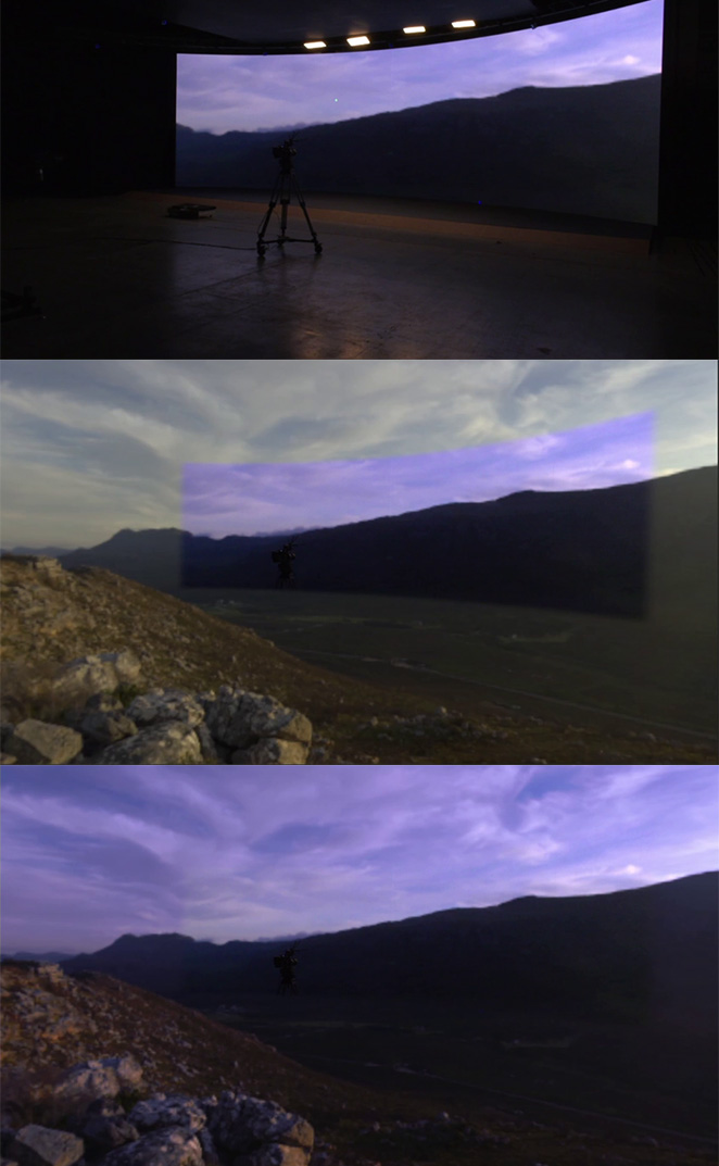
The picture below has been taken before and after applying a color calibration to the extended part :
How it works :
Just like the Geometric Calibration, SMODE will need one or several viewpoints of the setup, to determine the color correction to be applied to the extended part.
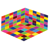
These viewpoints are not images but sequences of grids of different colors cast on the screens. SMODE will then compare each color sent in each square with the one received, and will then determine which is the color model of your setup.
Color model: the colorimetric profile of your setup.
2 - Before Starting a Color Calibration
- SMODE is fully optimized in graphical performances. Use the Profiling feature if needed.
- The frame rate is stable. If not, it might be because your set-up isn’t fully genlocked
- You are filming every impacted screen
- The camera doesn’t move
- Ensure that you have done a XR - Latency Calibration
- Turn off every light on stage
- Alert people not to pass in front of the camera
3 - UI Check-out
-
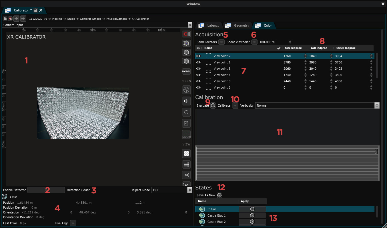
- Viewport : Displays the stream of the
 XR Calibrator
 Video Input
- Viewport : Displays the stream of the
-
- Enable Detector : Enables the detection of
 April Tag
and displays helpers in the viewport.
April Tag
and displays helpers in the viewport.
- Enable Detector : Enables the detection of
-
- Detection count : Number of
April Tag
detected. (Is a result of the
 April Tag detector modifier
- Detection count : Number of
-
- Tracker information : Display the current position orientation of the
 Tracker
of the
Tracker
of the
 Physical Camera
such as the deviation. A positive value of Position Deviation and Orientation Deviation means that your tracker is currently moving.
Physical Camera
such as the deviation. A positive value of Position Deviation and Orientation Deviation means that your tracker is currently moving.
- Tracker information : Display the current position orientation of the
-
- Send Locators : Display a
 April Tag Grid
in each Led screens.
April Tag Grid
in each Led screens.
- Send Locators : Display a
-
- Shoot viewpoint : Start the shot of a viewpoint for calibration
-
- List of Viewpoints : Every viewpoint appears in that list
-
- ViewPoints information : Display the number of
April Tag
detected for each screens and the pixel gap between their position in the video input stream and the stage simulation.
- ViewPoints information : Display the number of
-
- Evaluate : Make an average evaluation of the differences of colors between Emitted colors and Received colors
-
- Calibrate : Start a calibration. Calculation depends on the number of viewpoints shot.
-
- Console output
-
- Save as Calibration State : Save the calibration results as a calibration state.
-
- Calibration States list : Every calibrations result can be called back as a state. They appear in that list.
4 - Calibration process
In the XR Calibrator, Color tab, enable the Enable Locator.
Try to detect the highest amount of apriltags, especially at the junctions of the walls and the corners, as these are the places where there is the highest need to catch up on color.
Play with the focus of the camera to detect more of them.

There is also the possibility to change the “Quad Decimate” parameter (In -> Detector: April Tag) to increase the number of tags displayed in the screens.

You need to lower the Decimate value, that will allow the detection of more tags (but SMODE can slow down if your machine is not powerful enough)
Take a Viewpoint shot. Remove the locators before each viewpoint shoot to optimize performances.
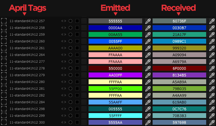
When a Viewpoint is taken, several different colors are sent to the screens at the level of each tag. Smode then records, for each detected tag, each color: the one that is emitted at this place of the screen, and the one that is received.
It is then able to deduce the difference between a color sent, at a given place on the screen, compared to the color received at the same place.
You can visualize the data of a Viewpoint by unfolding “Viewpoints” at the bottom of the color parameter of the XR-Calibrator :
Once your viewpoint has been shot, move the camera to get another point of view, wait for your camera to be stable, and take another shot.
You don’t have to look at all the screens for a viewpoint-shot. Look at the interesting parts of the stage to be calibrated.
Try to take viewpoints seen from the front of the screens, as much as possible. Feel free to shoot twice on the same position. The colors sent being randomized, this can improve the quality of the measurements.
If you have a fixed position camera make one or multiple shots from it’s position.
In some cases, it can be interesting to “merge” the color models of the screens that make up the walls of your setup.
Select the corresponding
 XR Display information
and then in Color Model -> General -> Type -> Switch to Merge.
XR Display information
and then in Color Model -> General -> Type -> Switch to Merge.
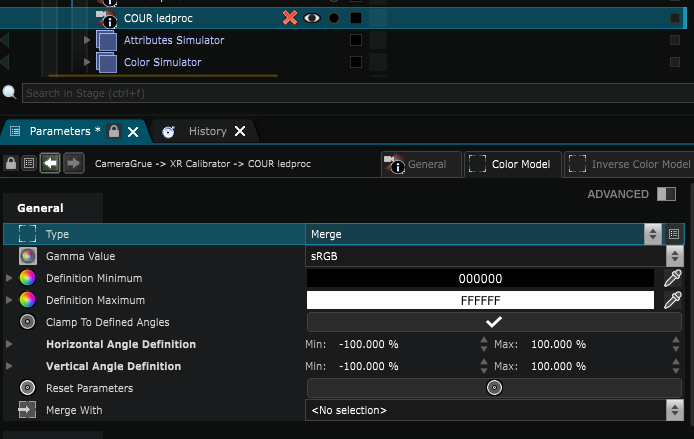
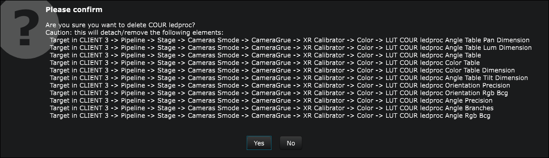
A panel warns you that several target parameters will be deleted. Press “YES”.
In the
XR Display information
, merge the color model of one screen with the other one.

You are now ready to start a calibration. Press Calibrate :
By default only the color model is calibrated, the inverse color model is a lot more complex to setup to have good results with. It also takes a lot more time to Calibrate.
The calculation generates a collection of LUTs stored in the
XR Display information
and can be applied to your setup using a
 Smart Lut
.
Smart Lut
.
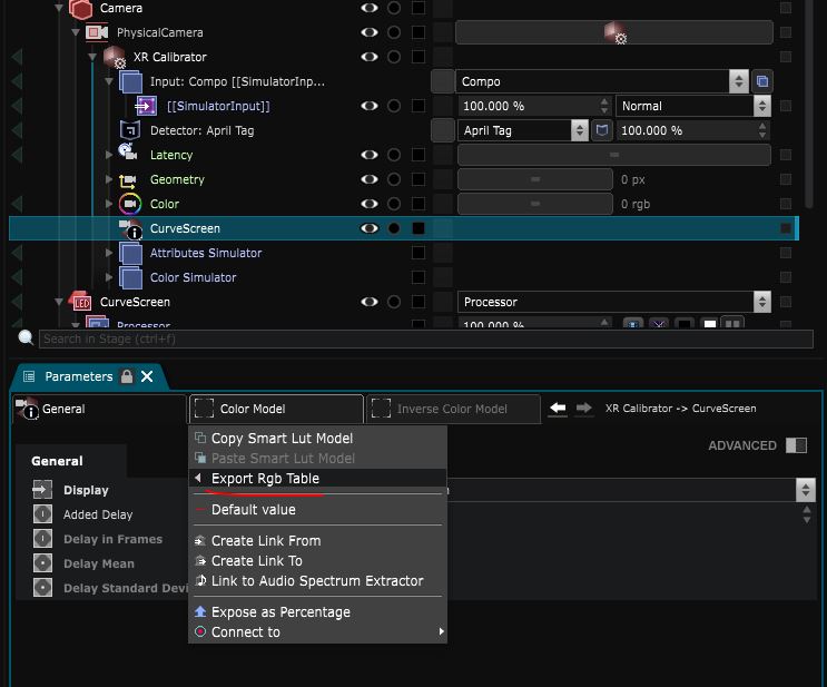
6 - Export the Calibration data
Just like the XR - Geometry Calibration , you have the possibility to save your color calibration into a .smartlut file. Those files can be re-imported later.
7 - Applying the Calibration
At this step, you’ll have to modify the colors of your AR and Extension compositions to make them match the colorimetric profile of your setup.
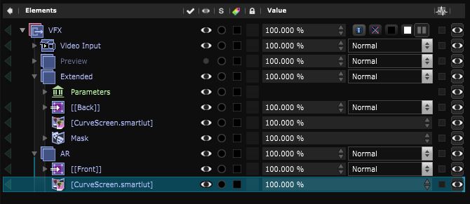
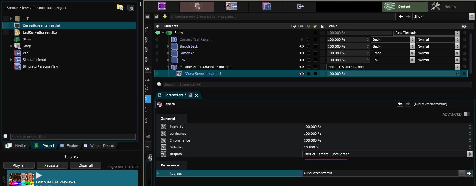
You can drag and drop the .smartlut you just exported : it will create a
Smart Lut
that you can apply directly onto the Extended and AR compo in your VFX processor:
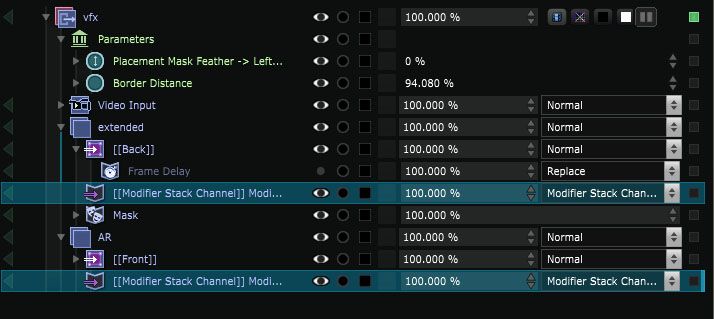
Or you can use a
 Modifier Stack Layer
so your color controls are centralized in your show and you can adjust them by hand :
Modifier Stack Layer
so your color controls are centralized in your show and you can adjust them by hand :
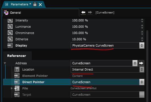
Once you’ve imported a
Smart Lut
you need to select the Display (for the optional angle data) :
If you want to directly connect the LUT to the display without exporting it, you can create a
8 - Correcting the LED color depending on the angle
The
Display Angle Mask
can also be helpful because it’s role is to mask any
 2D Modifier
or
2D Modifier
or
 2D Generator
according to the angle of the selected
Stage Elements
angle.
2D Generator
according to the angle of the selected
Stage Elements
angle.