Camera Tracking
Create and configure a Tracking System and Physical Camera
Physical Camera requires a specific XR/AR license.
If you’d like to try out these features to decide whether you want to purchase an XR/AR license, please contact us.
Create a control device
In an XR or AR project, Smode needs to know the position of your camera in real-time.
This allows Smode to synchronize the movement of the virtual camera in 3D space, ensuring that the image on the LED screens is consistent from the camera’s perspective.
To obtain real-time information about the camera’s position, you need to use a tracking system.
Ensure that your tracking system is properly configured and calibrated before connecting it with Smode.
To establish a connection between your tracking system and Smode for real-time data retrieval, you must create a
Control Device
in the
Preferences panel
panel.
Click the Add button to create a new Control Device, and select the type of tracker you are using from the list.
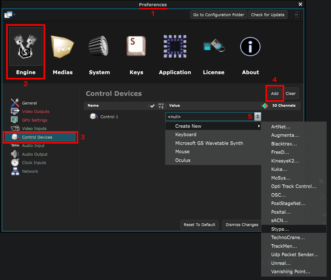
In this example, we will use a Stype Tracking Device.
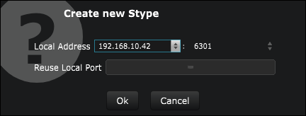
Configure the address and port of the device. If another application needs to access the data of this device, check “Reuse local port”.
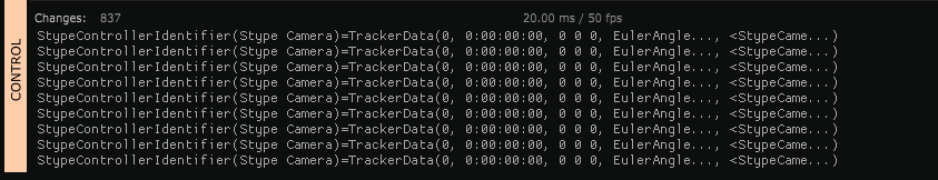
Once your device is configured, you should see incoming data in the
 Devices Panel
:
Devices Panel
:
Create a tracking System
In the
 Stage
, create a
Stage
, create a
![]() Tracking System
and place it above other stage elements.
Tracking System
and place it above other stage elements.
Select the tracking
Control Device
you created from the list of devices in the tracking system’s settings.
![]()
![]()
A
![]() Tracker
will be created in your tracking system.
Tracker
will be created in your tracking system.
If your tracking system is positioned below other stage elements, you may encounter issues during the calibration process.
Create a physical Camera
Create a
Physical Camera
. It is a specific camera designed to simulate a real one. By default, it’s placement is of the
Link To Tracker
type.
Select the
![]() Tracker
associated with your camera.
Tracker
associated with your camera.
![]()
![]()
Place the camera in a
 Stage Elements Group
and position it in between the tracking system and the LED screens.
Stage Elements Group
and position it in between the tracking system and the LED screens.
Layers order
At this point, all the necessary Stage Elements have been created. To ensure your calibration works, please follow this order of layers :
- Tracking System
- Physical Camera
- Floor LED screen
- First LED screen wall
- Second LED screen wall
Example:
- Correct:
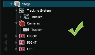
- Correct: the positions of the LED screen walls are interchangeable:

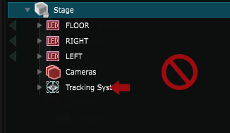
- Not correct: the tracking system isn’t in first position in the tree:
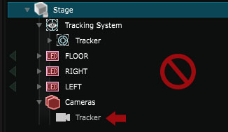
- Not correct: the Camera isn’t in second position in the tree:
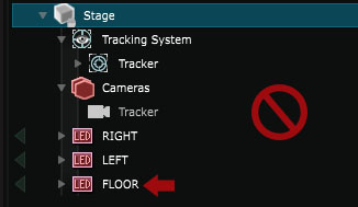
- Not correct: the Floor isn’t the first LED screen:
You can now proceed to the next step: XR - Broadcasting 3D content on the LED screens .