XR - Geometry Calibration
Lets Smode know the position of cameras and Led Screens in the real world
XR - geometry calibration needs a specific XR/AR license.
If you’d like to try out these features to decide whether you want to purchase an XR/AR license, please contact us.
1 - Theory
How to let SMODE know the positions of cameras and screens?
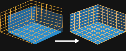
Geometry Calibration will enable SMODE to detect the positions of the screens in the real stage, and adjust the virtual one.
The calculation works thanks to
 April Tag
and
April Tag
and
 April Tag detector modifier
, called Locators
April Tag detector modifier
, called Locators
The geometry calibration part consists in taking a sufficient number of shots called Single Frames of different points of view of your real stage with
April Tag
broadcasted in screens.
During this step, you will have to do succinctly:
- Take a shot (= store an single frame)
- Move the camera
- Wait for the tracker Position&Orientation deviation to be at 0 ( or a very low value )
- Take another shot (= store an single frame)
- Move the camera
- Wait for the tracker Position&Orientation deviation to be at 0 ( or a very low value ), again
- etc

You don’t have to store frames that display the entire screen. But be sure to detect enough
April Tag
. You can modify the focus of your camera if needed.
2 - Before Starting a geometric Calibration
Before launching the latency calibration, you must ensure that :
Check that the Camera position and orientation in the
 Stage
is approximately the same as in the Real Stage
Stage
is approximately the same as in the Real Stage
For this you can:
- Ask the people who set up the tracking device where de 0 is on the real stage. And place the
 Tracking System
to this point.
Tracking System
to this point. - Move the camera up-down, front-back, and left-right axes. And rotate, if needed, the
Tracking System
according to your observations.
- Pan and tilt the camera to verify that it’s looking in the same direction, if not, you’ll need to offset the orientation of the
 Tracker
![]()
![]()
Once you’ve ensured the previous points, you can start a geometry calibration.
2.1 - For Stype tracking systems
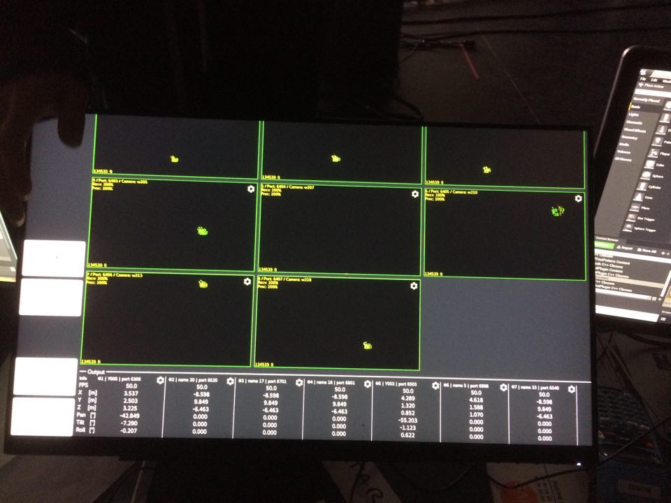
- [On Stype world]: Ensure that the camera position is correctly supported by Stype (seen by all cameras). Example below is not good:
- [On Stype world]: Calibrate the min and max zoom of the Stype Computer.
2.2 - For FreeD tracking system
You need to report the maximum and minimum values of zoom on your Camera model. Zoom in and out until the greatest values for min and max are reached.
Verify if the values set in the Custom Zoom Interval are correct.

If not, you can set them manually.
3 - UI Check-out
Go to the Geometry Tab of the
 XR Calibrator Editor
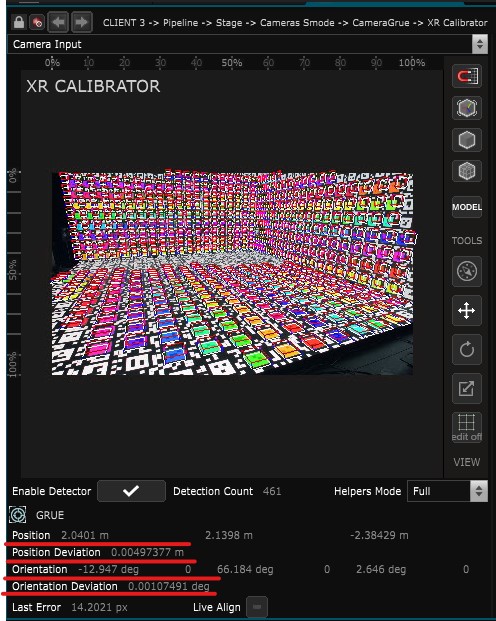
- Viewport : Displays the stream of the
 XR Calibrator
 Video Input
- Enable Detector : Enables the detection of
April Tag
and displays helpers in the viewport.
- Detection count : Number of
April Tag
detected. Is a result of the
April Tag detector modifier
- Tracker information : Display the current position orientation of the
Tracker
of the
 Physical Camera
such as the deviation. A positive value of Position Deviation and Orientation Deviation means that your tracker is currently moving.
Physical Camera
such as the deviation. A positive value of Position Deviation and Orientation Deviation means that your tracker is currently moving. - Send Locators : Displays an
 April Tag Grid
in every LED screen.
April Tag Grid
in every LED screen. - Store Single Frame : Trigger to store a frame for calibration
- List of single frames : every single frame appears in that list
- Single frame information: displays the number of
April Tag
detected for each screen and the pixel gap between their position in the video input stream and the stage simulation.
- Evaluate : Make an average evaluation of the pixel gap
- Calibrate : Start a calibration.
- Console output
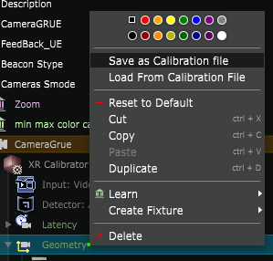
- Save as Calibration State : Save the calibration results as a calibration state.
- Calibration States list : Every calibration result can be called back as a state. They appears in that list.
Learn more about XR - Geometry Calibration
4 - Calibration process
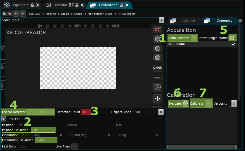
Enable “Send Locator” (1)
Wait until the “Standard deviation” parameter for Position and Orientation reaches 0 (2).
This data represents “jitter” in the signal output from your tracking system. Either the camera isn’t stable yet, or there is a problem, verify with the people who set up the tracking system.
Verify that a sufficient number of tags are detected (3). If necessary, adjust the Focus and use the Enable Detector function (4) without being On-Air to view the detected tags in the viewport
Then you can Store Single Frame (5).
Move the camera for the next frame, then wait until it is stable (Position Orientation Deviation), then store a new Single Frame (5).
These last steps need to be repeated several times.
When you have multiple frames :
you can press Evaluate (6) and delete or mute frames with error amounts that are above the average.
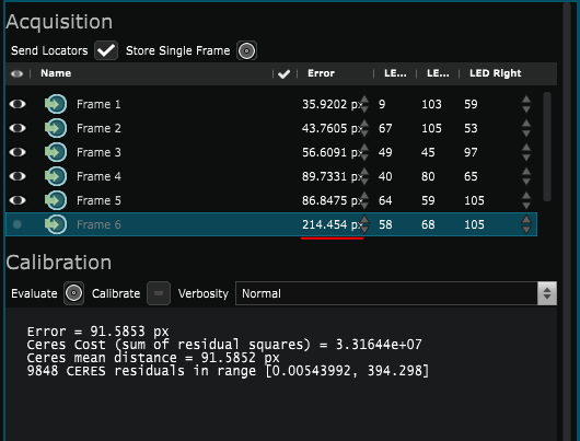
Once you have verified your frames press Calibrate (7)
Wait until the toggle is automatically unset at the end of the calibration
4.1 - Stype Calibration process
When using Stype you need to chose if you want to use the optic data from Stype or calibrate a Prime lens optic in SMODE in your
Physical Camera
with the mode parameter
4.2 - FreeD Calibration process
FreeD Calibration takes time ( 30 min to 1 hour )
-
Roughly place the position and orientation of the tracking system in the stage
-
Scan zoom to get the min & max zoom => c.f. display in the Physical Camera “custom zoom interval
-
a) Go to a wide zoom level and capture multiple frames with different orientations so that we cover the 4 corners of the camera image with april tags., do it for 3 different positions
b) Verify the the polynomials Fov, K1, k2, ShiftX, ShiftY are at degree 0 and press Calibrate
-
a) Staying in the current position is to engage different new zooms, covering the whole matrix of the detection camera, with the whole matrix of the detection camera, especially in the wide shots (=> 8 frames in total)
b) Calibrate with degree 2
c) Calibrate with degree 4
-
a) Look for problematic areas, make more frames
b) Calibrate with increased degree
c) Go back to 5a if there are still problematic areas
To save your Camera model, please check
Physical Camera
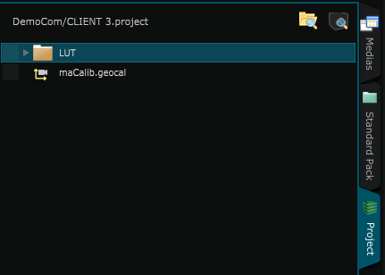
5 - Export Calibration
If you are satisfied with the calibration, export it. This will create a .geocal file directly in the SMODE project.
6 - TroubleShoots
- Try calibrating with only one frame enabled
- Verify that the screen are connected to the right output
- Verify your UV if you are using Fbx File
- Verify that the orientation of the screen is correct (with a test pattern for example)
Video Tutorial
Here is a video tutorial that uses a simulator, so you can learn the calibration process without a real Stage
You can download the project file here:CalibrationTutoStart.zip
You can also learn the calibration process for FreeD with Zoom
Download the project file here:CalibrationTutoFreeD.project.zip
Next step: XR - Color Calibration