Create a full multi LED pipeline from scratch
Send content into multiple led screens
The purpose of this topic is to create a full setup allowing to send content from the Show into pixel maps defined into multiple outputs.
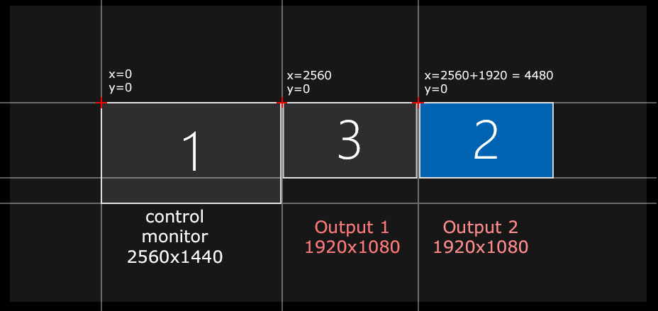
In our case we will have two outputs in HD and a control monitor in WQHD (2560x1440).
We are going to fit several led screens with various resolutions, in our two HD outputs .
This way of creating a diffusion pipeline into Smode has been used numerous times through TV shows and live events.
This Creation Pipeline allows to:
-
Ease the creation process with well organized content maps and stage pre-vizualisation
-
Create pixel mapped outputs to make the bridge between the content creation side (Content Maps) and the diffusion side (Processors)
-
Show in-context pre-vizualisations to clients
-
Display gap-less content on several screens thanks to
 Content Mapping
Here is what will be reviewed during this process:
-
Configure several Video Output Device
-
Create a new Project and build
 Content Map
and
Content Map
and
 Content Area
-
Create
 Processor
to create the pixel map from the content maps with
Processor
to create the pixel map from the content maps with
 Pipeline Layer
-
Connect the Processors to the video Outputs
-
Create a 3D
 Stage
simulation
Stage
simulation -
Create a stage pre-visualization with the
Processor
you can connect to an output -
Use a
 3D Camera Mapping
to display seamless content and open some door to interactive design
3D Camera Mapping
to display seamless content and open some door to interactive design
At the end of this tutorial there is a short video showing the whole process, to make sure you didn’t miss anything.
Introduction : Pixel outputs and Stage setup
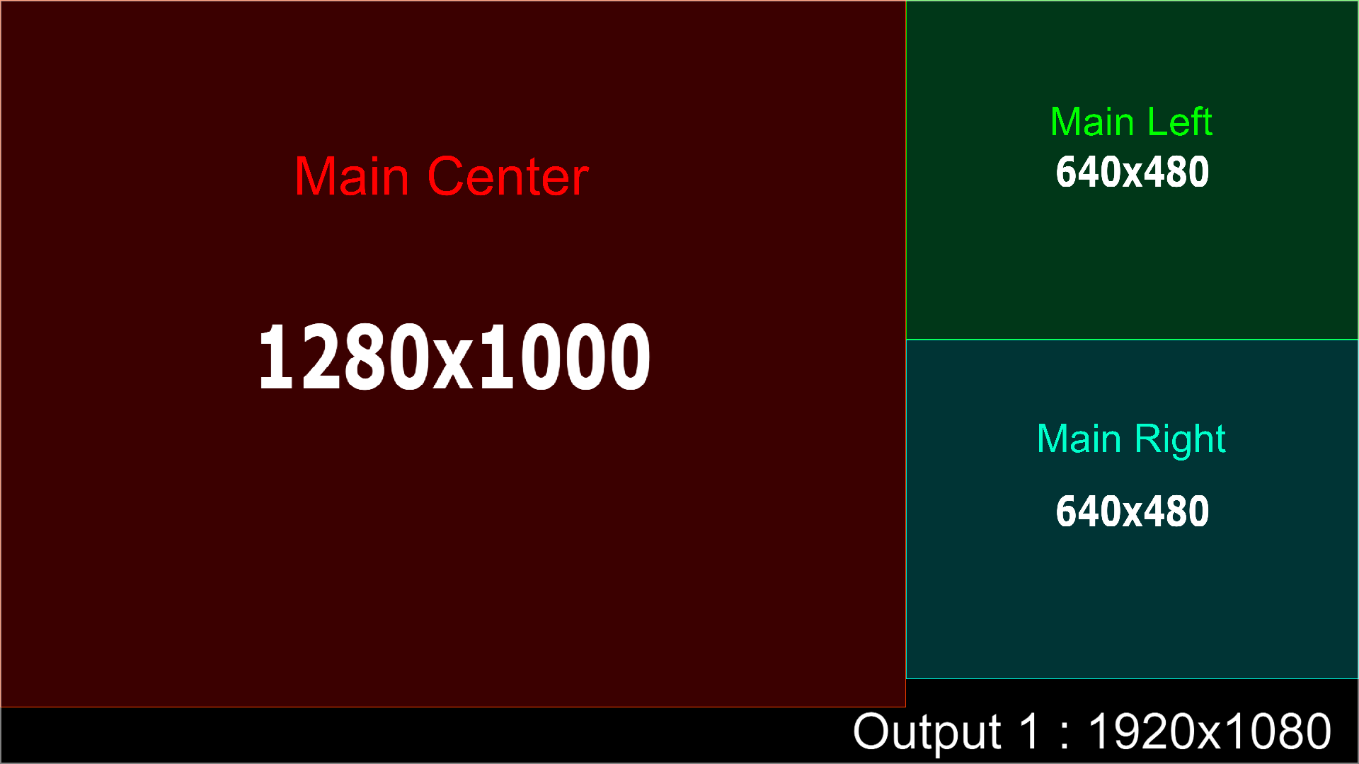
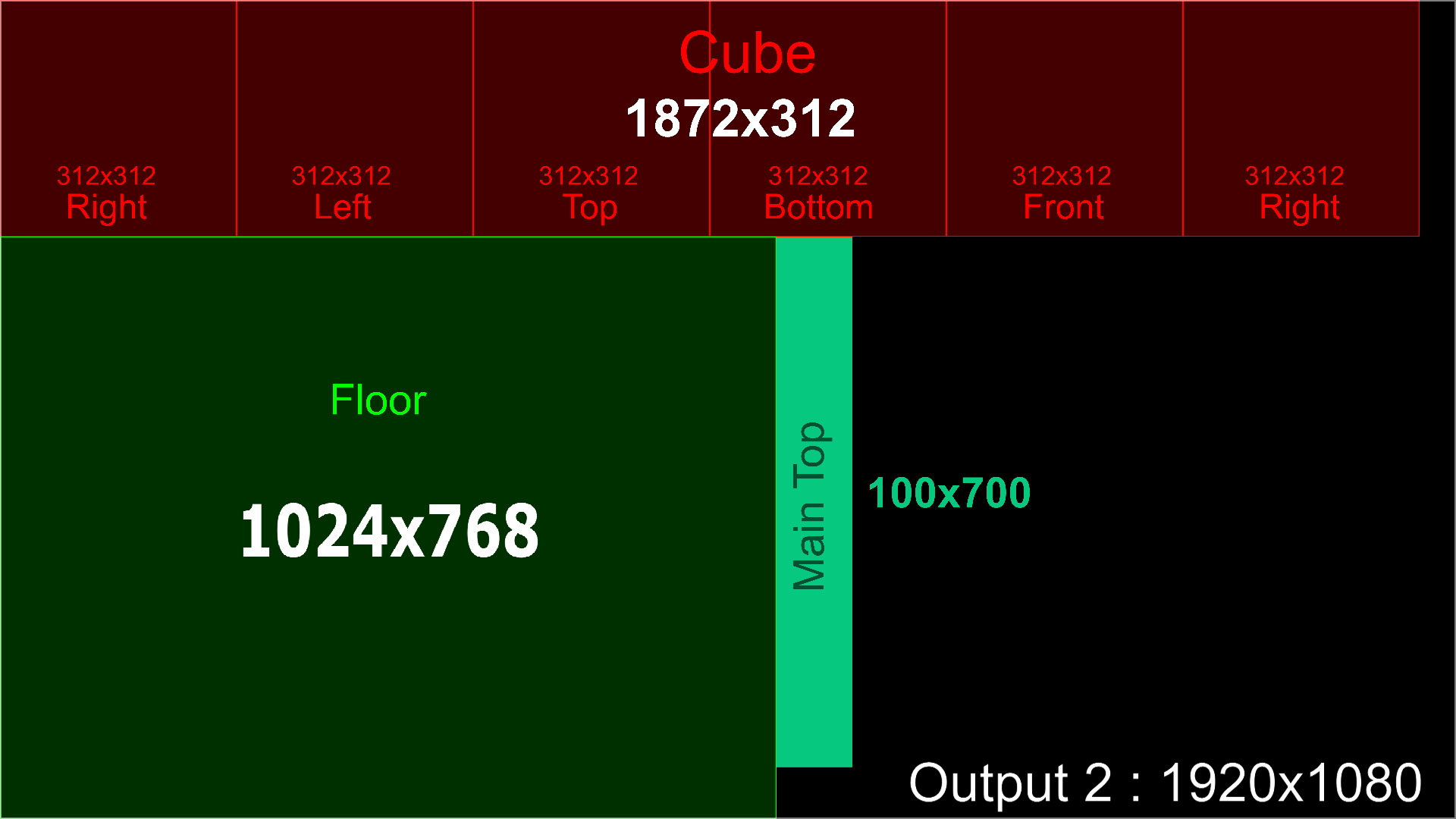
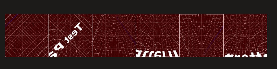
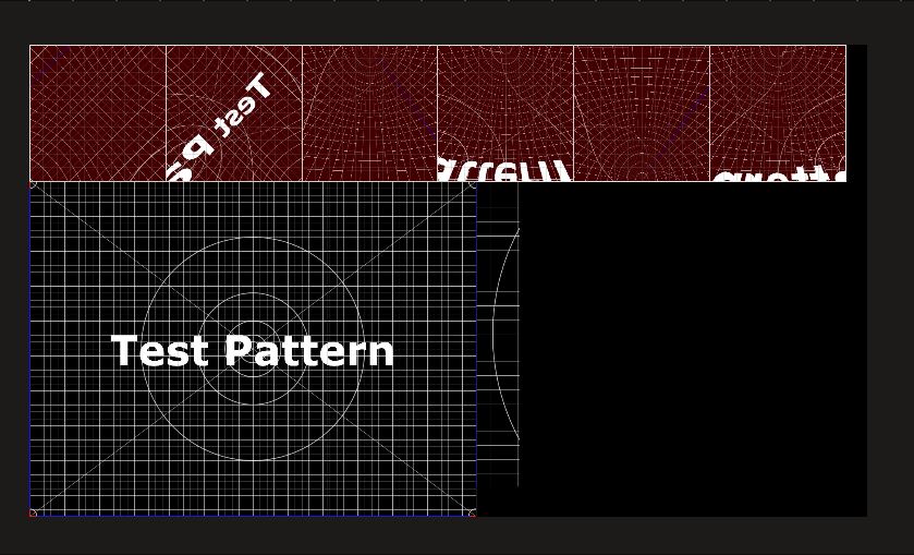
Here are the pixel maps we are going to use:
And here is what the 3D stage will look like:
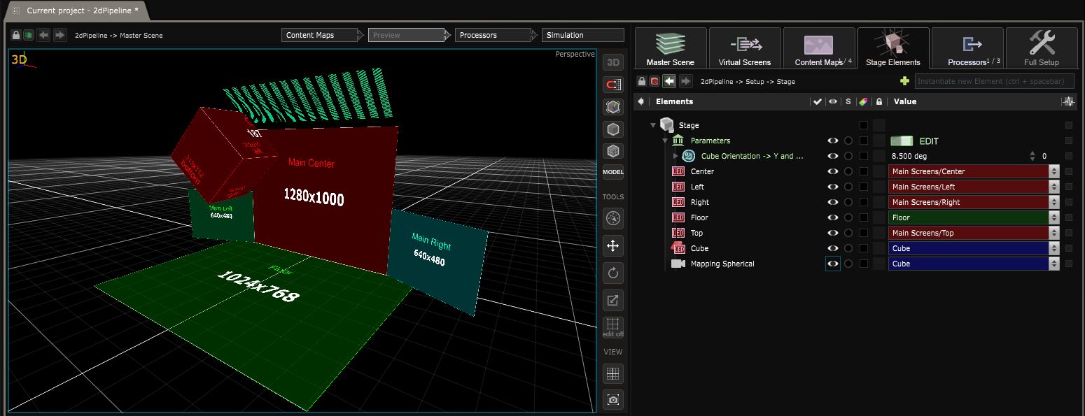
In our stage, we have the following elements:
Main Center / Main Right / Main Left : 6mm pitch LEDs
Floor : 10 mm pitch Led
Main Top : 14 small led with a 25x100px resolution, 6x20mm Pitch and separated from each other by 250mm
Cube : 2 meters wide led cube with 312x312px resolution on each face
Configure outputs in Smode and Windows (00:00)
First in Windows, do a right click -> display settings -> advanced display settings. Make sure that your output positions are aligned inside windows.
This step is important as this is the output coordinates we are going to use inside of Smode.
Make also sure that:
-
All your outputs fit inside the lowest possible resolution (see also the
 Video Output
part of the documentation).
Video Output
part of the documentation). -
Your global output window does not overlap your control monitor.
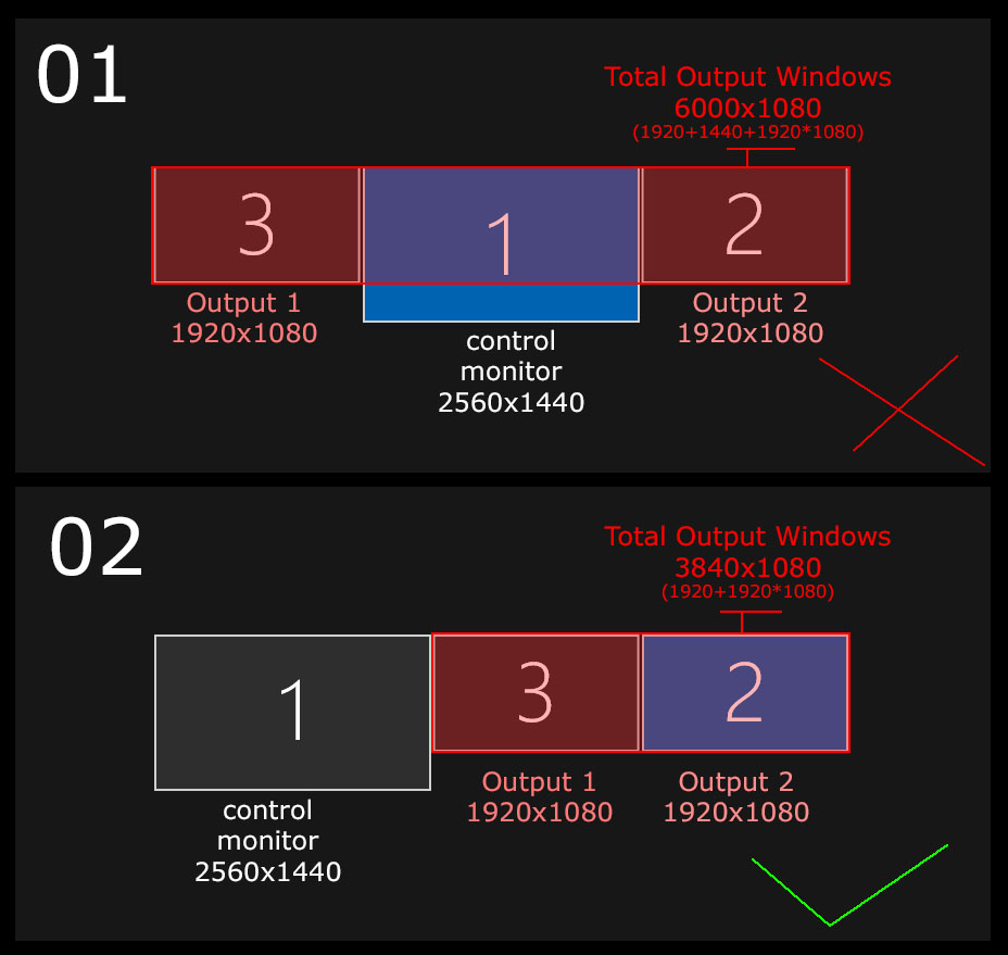
Once it’s done, we can now configure these 2 HD outputs inside Smode. To do that go inside preferences (F11) -> Video Outputs and add 2 new video Outputs and make them fit to monitor 2 and 3:
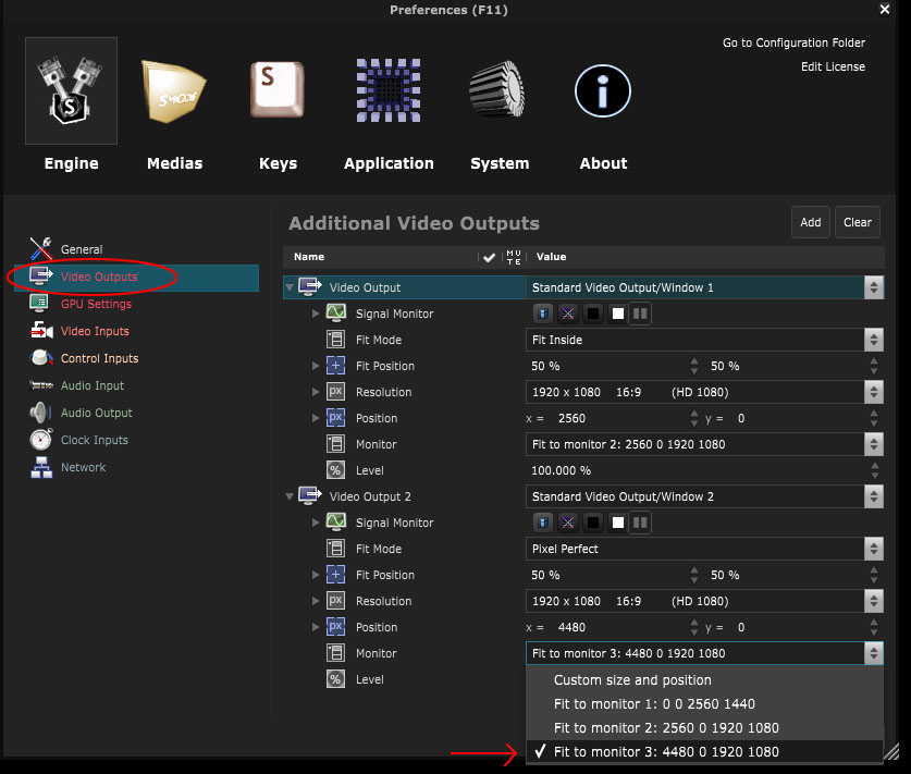
As you see here, the monitor position and resolution are defined here inside the ouptut configuration. Here the second output has a position of x=4480 y=0 and a HD resolution
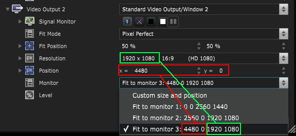
As defined in our windows output configuration:
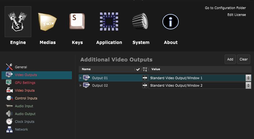
Apply changes and as a last step rename the video Outputs as “Output 01” and “Output 02”.
Create a 2D pipeline with multiple outputs (00:47)
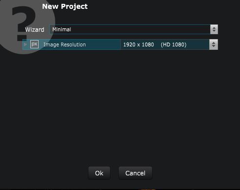
Create a new project with File Based Generators New project and choose the Minimal project with default settings:
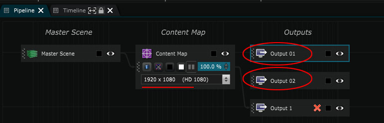
So we now have a project containing one HD
Content Map
and our 2 HD video outputs:
The first thing we’re going to do is to manage the
Content Map
organization.
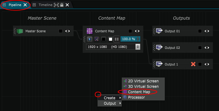
To create one, do a Right Click -> Create -> Content Map inside the
 Pipeline
:
Pipeline
:
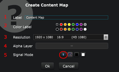
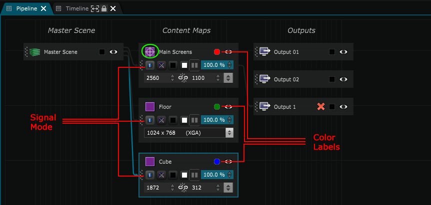
Each time you create a content map you can:
1 - Change it’s name
2 - Change it’s color label (this way each target will have a specific color inside the Show )
3 - Change the resolution (here you can change to “custom” at the bottom of the list
4 - Define an alpha background for the content map
5 - Change the signal mode of the content map (here I will put the signal as “content” for each content map so we will be able to send layers to them from the Show .)
This step is a process regarding the content creation for the designers and should be set up to ease their creation process, independently of the output map.
We’ll create 3 different content maps. One for the cube, one for the floor and one for all the main screens.
The main screens content maps total resolution will be a sum of it’s components:
x=640+1280+640=2560
y=1000+100=1100
For the y resolution of this content map, the “+100” part is due to the fact that inside our content maps we will rotate the “main top” output as on the real stage this surface is displayed horizontally. This will make the work easier for the content designer.
So my main screens content map will be of 2560x1360 with a red color label and a “content” signal mode
The floor content map will have a resolution of 1024x768 with a green color label and a “content” signal mode.
For the cube content map we will have a resolution of 1872x312 with a blue color label and a “content” signal mode.
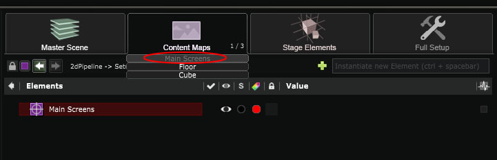
You should have something like the screenshot below. In the green circle you can see an Icon representing the default “content map”.
This mean that when you’ll create a new layer inside the
Show
, it will automatically be sent inside this content map.
To change the defaul content map (default target of the
Show
), right click on the content map -> set as default target.
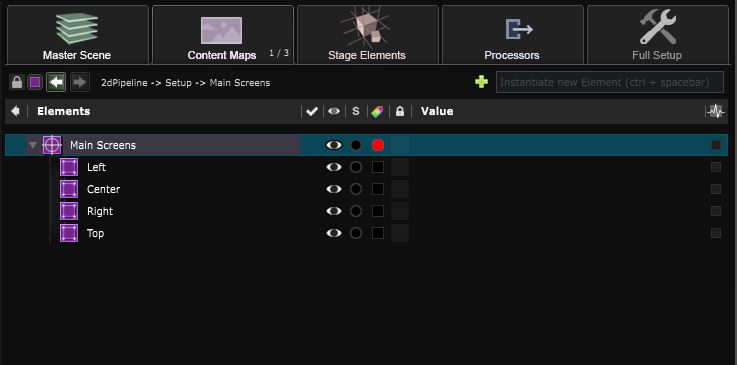
Now lets go inside each of our
Content Map
and split them into different
Content Area
s corresponding to our different screens:
On the “Main screens” content map we now have 4 content areas: center / top / left / right.
To create a content area, “right click on the root of the content map -> Content area”.
For the content area to be easier to place, transform their Placement in order to have an Anchor point at 0px / 0px.
To change the resolution of the content areas, go inside their placement parameters, turn the “placement-Scale” parameter into “size” and enter their values in px after having changed the global units values in pixels.
Here is an example on how to place the left screen inside the content map :
Here are the values given to each content area. Focus on the position and scale (in pixels), as every Anchor point as been set to 0px / 0px:
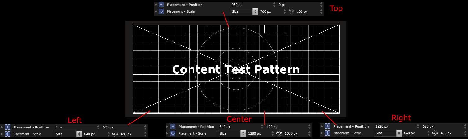
Let’s rename these content areas in Left / Center / Right / Top, so it will be easier for us later on.
Now let’s go inside the “Cube” content map. This time, defining the content areas will be easier. As our cube is split into 6 equal areas, just select the root of the cube content maps and “right click->split horizontally”.
And now your content map is split into 6 equals content areas. Let’s rename them with more friendly names, top / bottom / left / front / right / back
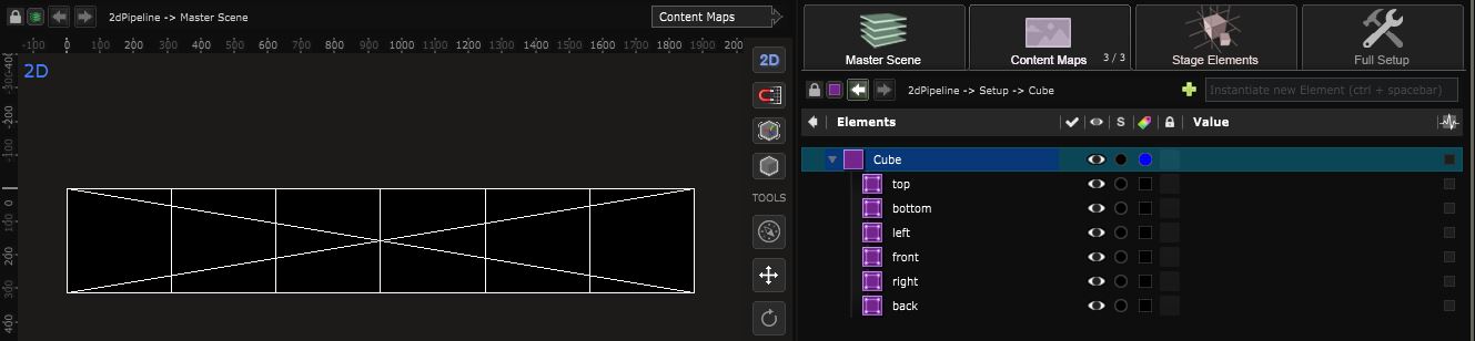
The last content map will remain unchanged.
Now if we go back inside the
Show
we see that every
Content Map
and
Content Area
is available as a target for any content with it’s own color label:
The content Map process is here to help content designers , it define the pixel workspaces in which you will be working. Now we can either send a content into my main screens altogether or to a specific screen only :
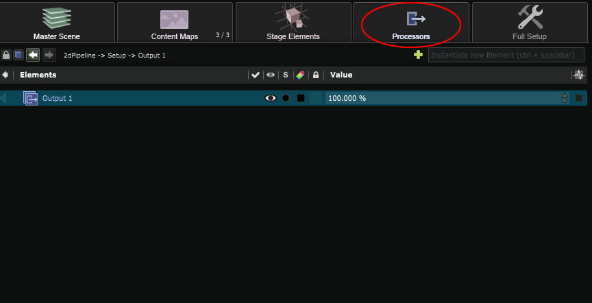
Now comes the time to define our outputs. For this we will use the
Processor
:
Let’s start with the first output and create a HD Processor we will rename “Output 1”.
To do that go inside the
Pipeline
and “Right Click -> Create Processor” :
And click on the Processor Tab to access this processor:
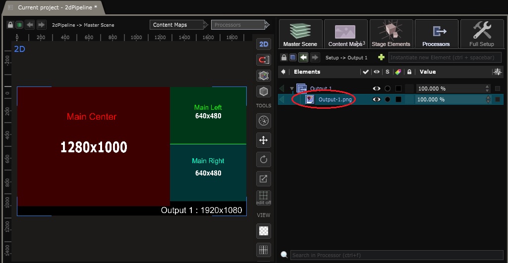
Now let’s Import our content area to make them match with the pixel map.
For that, let’s import our pixel map as the background of this
Processor
by dragging it into it’s
 Element Tree
from the
Element Tree
from the
 Media Directories
.
Media Directories
.
If you don’t know how to configure the media directories, please refer to that part of the documentation.
Now we are going to put the corresponding content areas and content maps into this first output. To do that, inside the
Processor
’s
Element Tree
do a “right click -> Pipeline Layers” and select the right layers.
These
Pipeline Layer
are only available inside of processors and allow to get any content map or content area.
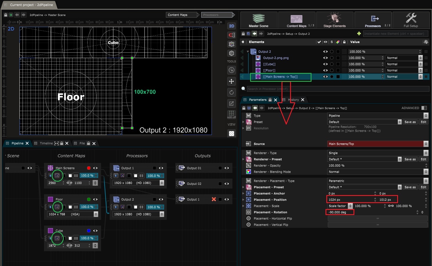
Repeat this process for the second output. On the following screenshots, you can see the position parameters I used for the “main top” area (red squares).
I also temporarily switched the “signal mode” of the content maps from “content” to “test pattern” (green circles), to have a better understanding what’s going on.
Now that these two processors are configured, you can delete the pixel map from the processors, and connect each processor to the outputs we previously configured:
We now have a fully working 2d pipeline.
Create a 3D stage simulation (10:24)
Now that all our
Content Map
and
Processor
are ready, we can start creating the 3D stage simulation. This will serve many different purposes.
First let’s have a nice visualisation of how our creation will look like in the actual stage, allowing to adapt and fine tune content creation before going on site.
The second point is to place the screens and projection surfaces in the right position in a 3D space in order to enhance 3d mapping inside the creation process.
First let’s build the
Stage
and then we’ll build some
Content Mapping
.
To create a stage element, such as a
 Led Screen
, do a right click inside stage tab and choose a
Planar Led Screen
. Then a bog will open asking you to choose which content map will be displayed on that screen :
Led Screen
, do a right click inside stage tab and choose a
Planar Led Screen
. Then a bog will open asking you to choose which content map will be displayed on that screen :
Note that the
Led Screen
will automatically adapt it’s resolution from the
Content Map
we connected it to. Then, inside the
Planar Led Screen
parameters you’ll find pitch and size information.
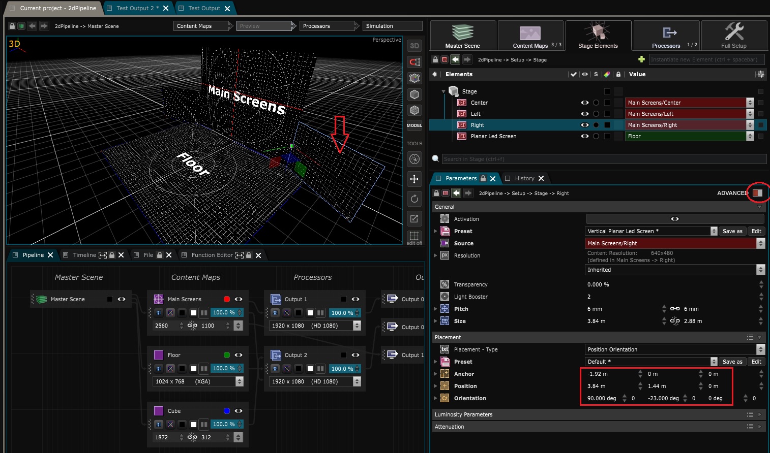
Here we will consider that every screen (except for the “main Top”) are 6mm pitch LED screens. Now let’s repeat this operation and place the left / right screens as well as the floor.
Place them as you want in your stage, here is how this one looks like, placing the 0 point on the center bottom of the main central screen.
On the screenshot below you’ll also see how i placed the right screen. Again, make sure to look at the video at the end of this tutorial if you don’t want to miss anything.
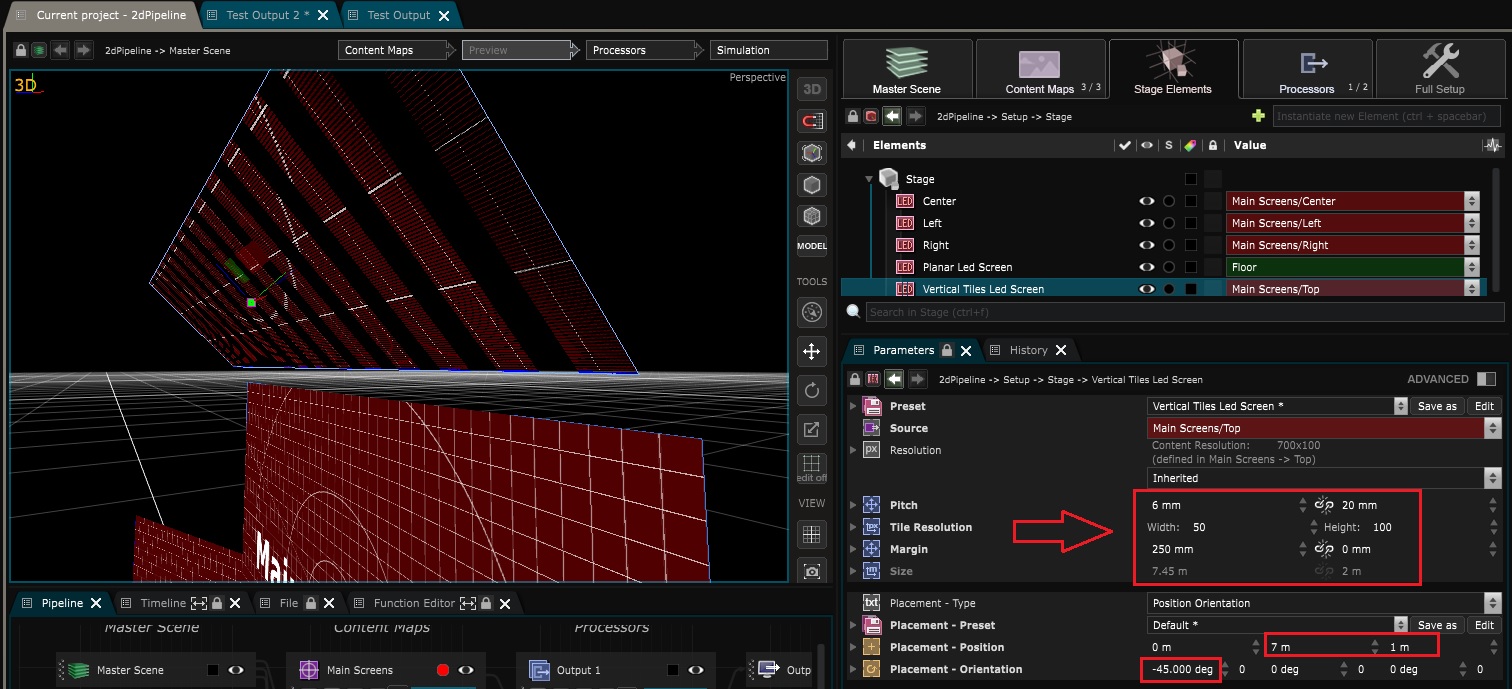
Now let’s place the bottom screen which has a particular setup. In order to simulate it well, we are going to use a
 Tiles Led Screen
instead of a
Planar Led Screen
:
Tiles Led Screen
instead of a
Planar Led Screen
:
This
 Strip Led Screen
will allow us to simulate led screens with particular settings.
Strip Led Screen
will allow us to simulate led screens with particular settings.
As this top area is constituited of 14 small led with a 25x100px resolution, 6x20mm Pitch and separated from each other by 250mm, here is the setting put inside the
Tiles Led Screen
parameters :
All that remains now is the cube. We will use a
 Free Shape Led Screen
.
Free Shape Led Screen
.
The difference between this led screen and the other one is that with this one we cannot simulate the pitch of the LED, that’s why we will have to enter the cube size manually, in meters.
-
Right click -> Elements -> Free Shade LED screen
-
Change “Geometry Type” to “Box”
-
Finally, change the “Geometry UV mode” to “Horizontal Split”
Note that we used a
Free Shape Led Screen
because the geometry is simple. If you have a complex LED screen sculpture, you may have to use a fbx with unfolded UVs instead.
Here is a little Tip, to quickly send a test pattern in an element. For that purpose, we’ll use the “Signal Mode” of the
Content Map
:
And here you have it, the stage is created!
Create a 3D stage pre-visualization of the simulation (15:29)
To create a previsualisation, we are going to create a new
Processor
in HD that we’ll call “Previz”.
Now that we have a 3D stage simulation, we can get it back inside the processors as a
Pipeline Layer
and create a
 Camera
:
Camera
:
From now on, you have every compositing tools available to make this stage pre-visualization look prettier. You can also import some
 3D File
to add details (such as stage elements / artists etc.)
3D File
to add details (such as stage elements / artists etc.)
You just have to connect this previz processor to any output to have a stage pre-vizualisation for client demonstrations or simply for working and creating content.
Use the simulation to display content through content mappings (16:56)
Here we will create a new target inside the
Show
that will display content around the cube using a spherical mapping.
For that we’ll use a
3D Camera Mapping
inside the stage simulation and use it deform the medias inside the content map.
First let’s create a Mapping Item inside the stage, set it as “Spherical” and place it in the center of the cube :
Now create a
3D Camera Mapping
inside the
Pipeline
, give it a 2K resolution. Inside it’s parameters, choose the “Spherical Mapping” as Mapping.
Let’s rename this
Content Mapping
as “Spherical Mapping” and gave it a color label in order to better identify it’s target inside the
Show
later on.
Now you see that we have a new “Spherical Mapping” target inside our Show , in which we can send any new content :
To discriminate the surfaces in which we want this
Content Mapping
to apply, we’ll just have to move elements inside it’s parameters from the impacted elements (bottom part) to the excluded ones (top part of the parameters).
Here we excluded every surface from the
Content Mapping
(except for the cube) :
Another tip, if you want to be sure that your content fits the whole
Content Mapping
, right click -> Placement -> full over the content you’ll send through this target from the
Show
:
Now if you check back the content maps, you’ll see the deformations created by the spherical mapping:
Inside the Output Processors too:
To make that clear, here is what happen inside the stage simulations and content maps once we rotate the cube inside the stage elements. For that demonstration, we imported the cube’s content map inside the “previz” processor :
This technique has many purposes, the first one was to deform what we send through the content maps accordingly to the placement of LED screens in the real space, but we can also use this to create interactive installations.
Here I inverted the impacted elements of the
3D Camera Mapping
and linked the rotation of the cube and the spherical mapping using
 Exposed Parameter
:
Exposed Parameter
:
Now if you rotate this exposed value, here is what happens :
Now if we get back the real cube rotation information with any
Control Device
such as
OSC
, midi or whatever, and bind it to our
Exposed Parameter
, then we’ll have our interactive installation.
Please refer to our other tutorials for more use cases of the
3D Camera Mapping
.