Create a full 3D mapping project from scratch
Quick Video Tutorial
The objective here will be to create a full 3D mapping project using an imported mesh of the stage and virtual video projectors.
In our study case, we’ll have 3 projection surfaces, 2 totems and the floor. We got 4 HD Video projectors, but only one 4K output, that will be split later on (with an X4 for instance).
This Pipeline setup allows to:
-
Send content on the real model using the UVs of the 3D model
-
Use virtual video projectors to ease the deformation and warping process
-
Show in-context pre-vizualisation to clients
-
Create custom elements to display content as you want with 2D and 3D
 Content Mapping
Here is what will be reviewed during this process:
-
Create a new Project and build
 Content Map
and
Content Map
and
 Content Area
-
Use
 Video Projector
-
Use a
 3D Camera Mapping
to display seamless content
3D Camera Mapping
to display seamless content -
Create
 Processor
to create the pixel map from the content maps with
Processor
to create the pixel map from the content maps with
 Pipeline Layer
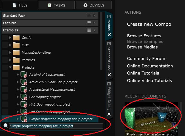
Here we will choose the minimal creation project wizard and try to build the project from scratch. The goal will be to construct this project from the example pack :
On the bottom of this page is a short video tutorial. This video is probably a little bit fast but in here there is everything for you to create a full mapping project with 3 video projectors sharing a single 4k output pixel map
In this tutorial you’ll learn how to do an advanced 3D mapping project in 15 min. Here is the step by step guide, you can jump directly to these parts by clicking in the YouTube video description :
00:00 - You must have a clean 3D model with unfolded and non-overlapping UVs. You can check
 3D File
for the specifications of imported 3D models.
3D File
for the specifications of imported 3D models.
00:27 - Create a new minimal project and enter the resolution of the default content map.
00:50 - Create 2
Content Map
, one for the floor and one for the Totems. At 01:07, the signal mode of the newly created content map “Signal Mode” is set from “test pattern” to “Input (meaning content from the
Show
)”
01:17 - Create 2
 Test Pattern
inside the
Show
and send each one into a different target (targets being the content maps, here “floor” and “totems”).
Test Pattern
inside the
Show
and send each one into a different target (targets being the content maps, here “floor” and “totems”).
Note that you can still change the “signal mode” of any content map back to “test pattern” with the icons of map module displayed inside the
 Pipeline
.
Pipeline
.
01:56 - Import the
3D File
and assign the content maps
02:05 - Assign a content map to each imported surface. The content maps will then be applied on the surface in function of their UVs
02:20 - Divide the totems
Content Map
in 2
Content Area
(one for each totem). As here my model is made to have each totem UVs unfolded on one side and another, so each
Content Area
will be assigned to one totem.
03:03 - Create a Camera in order to Create a
3D Camera Mapping
03:50 - Create the
3D Camera Mapping
module inside the
Pipeline
, choose it’s resolution and select as a projection camera the one we just created.
04:30 - Now This
Content Mapping
has become a new target on the
Show
, thus you can now send content through it.
At 04:32, the content sent through the
Content Mapping
is projected on the 3D stage simulation and the rewritten with correct deformations over the content maps.
05:18 - Create the
 2D Scene Mapping
module inside the
Pipeline
. This will allow to send medias from the
Show
to the Content Maps through a 2D transformation procedure.
2D Scene Mapping
module inside the
Pipeline
. This will allow to send medias from the
Show
to the Content Maps through a 2D transformation procedure.
What we try to achieve here is to have a new target inside the
Show
named “repeat all” that will repeat any content sent through it on each
Content Map
and
Content Area
.
Just duplicate the
 Parent Input layer
of the
2D Scene Mapping
and send it to every content map. Any transformation can be done inside a virtual screen, here I changed the color hue of the last parent input, targeted on the floor.
Parent Input layer
of the
2D Scene Mapping
and send it to every content map. Any transformation can be done inside a virtual screen, here I changed the color hue of the last parent input, targeted on the floor.
Now each time a content is sent through this “repeat all” virtual screen, it will be duplicated on each surface and have it’s color changed for the floor area.
06:44 - Create
Video Projector
and place them in simulation mode inside the
 Stage
. Here the projectors must be placed accurately with precise measurements and the right optic settings.
Stage
. Here the projectors must be placed accurately with precise measurements and the right optic settings.
Inside a video projector you can change throw ratio, FOV, lens shift and many other things. Lumens of the video projectors are only important for the simulation part but will not affect how your project will work in real life.
08:22 - Each Projector contains a
Processor
in which you can select which object (surface) of your stage this video projector will see and how. You can select to render some stage surfaces in black to create masks also.
09:01 - Create a new video Projector, here you can choose which surface it will see by default. You can still change that afterward by adding / deleting stage surfaces from the video projector Processor (as on the previous step).
10:55 - Here you can see I enter the view of a video projector so you can see what is happening when adding / deleting a stage surface of it’s processor.
11:15 - Here is the Lumens simulation mode. In Smode 8, the icon to enter this mode is no on the right bottom part of the
 Viewport
.
Viewport
.
11:30 - I chose for the floor projector to display the totems in black, so I will only project on the floor.
11:57 - And now let’s add some content :)
13:16 to 14:51 -UNNECESSARY STEP- Here you can see me adding content map into the video projector’s processors. You can do anything inside a processor, but to do this kind of mapping, better to use a standalone Processor than to mess inside the VP, as we will do in next step.
14:51 - Create an output pixel map composed with all your Video Projectors outputs inside of a
Processor
. A Processor allows many things, as Warping, Soft edges and Mapping,
but here the goal is to send 3HD signals into a 4K output, that will be then split to our 3 video projectors in real life.
15:53 - Select amongst the
Content Map
/
Video Projector
and
Processor
which one you want to send into the video outputs you configured inside the devices.