Stage Introduction
Learn how to create and configure Stages to accurately simulate your real-world environment, enabling you to visualize and fine-tune your project.
The
 Stage
is a virtual representation of your physical setup :
Stage
is a virtual representation of your physical setup :
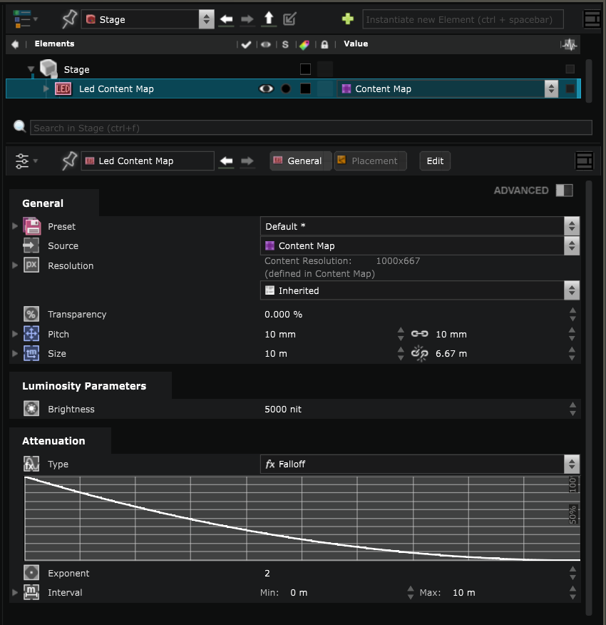
Create a
 Led Screen
A
Led Screen
Stage Elements
is a LED simulation that can simulate the pitch (the distance between the middle of each pixel), luminosity etc.
Set up the size and
 3D Placement
to match your real device.
3D Placement
to match your real device.
There are different
Led Screen
shapes available in Smode but you can also import a 3D file with a custom
Led Screen
shape called
 Free Shape Led Screen
.
Free Shape Led Screen
.
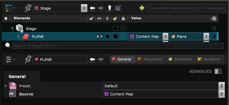
Create a
 Surface
A
Surface
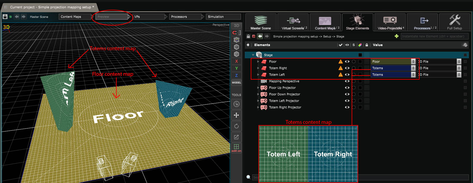
defines a surface on which you want to project some content with a video projector.
Choose what content you want to display on that surface by selecting a
 Content Map
Source.
Content Map
Source.
Import a 3D file as projection
Surface
You can create
Surface
in SMODE or import a 3D files in the
Stage
and select Reference as Surface to import custom shape
Surface
.
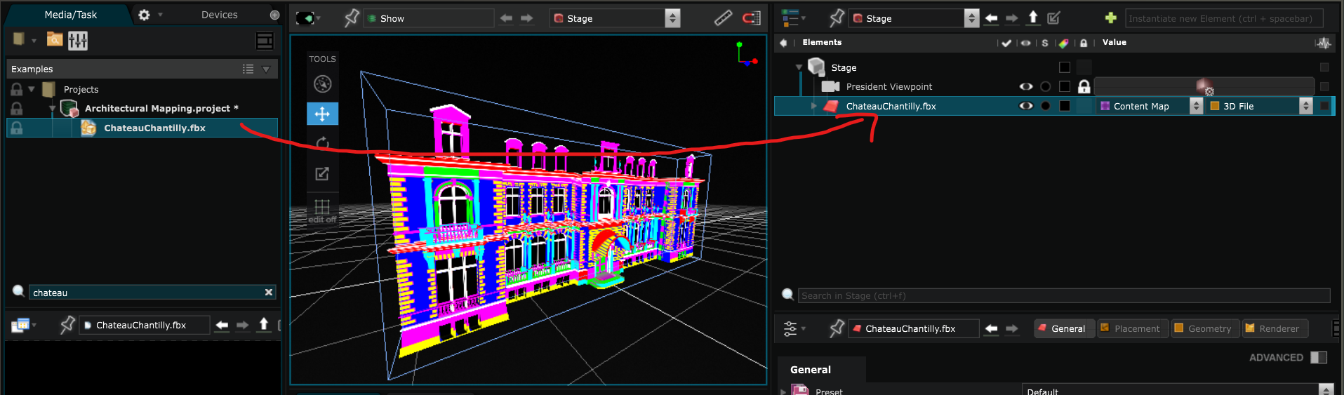
The imported geometry should have the minimum meshes possible. A file with too many objects will be impossible to manage and can produce lags or even crashes. Also remember to always flatten all the objects transformations prior to exporting.
The 3D models you’ll import into the Stage should only be elements you will be mapping on (either
Led Screen
or video projection
Surface
). If you want to add additional 3D elements to make a beautiful pre-visualisation (like the whole scene, the singers or whatever), read:
 Processor
chapter on stage pre-visualisation.
Processor
chapter on stage pre-visualisation.
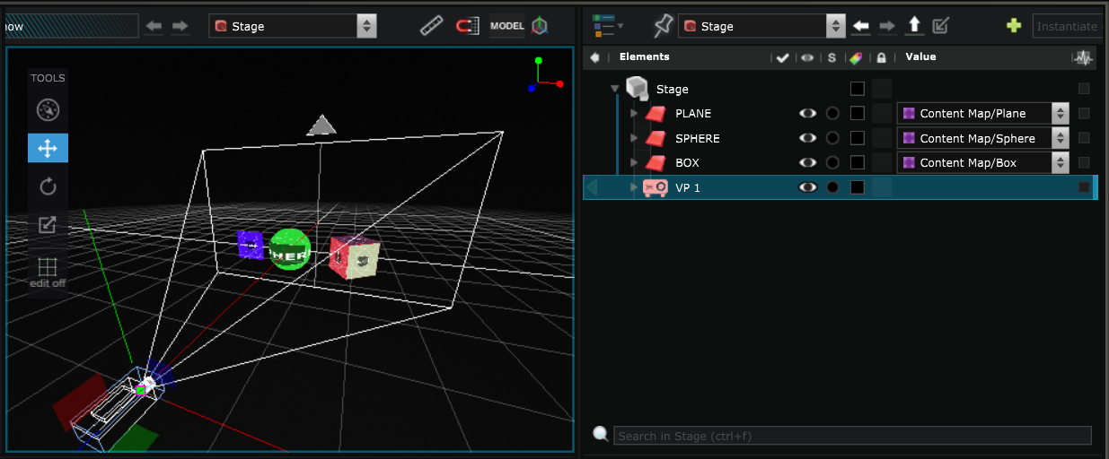
Once imported, define which content will be displayed where:
Create a
 Video Projector
Virtual
Video Projector
of SMODE’s
Stage Elements
are used for real life mapping and are usually directly connected to the
 Video Output
.
Video Output
.
You can learn more about it by reading :
Video Projector
.
When you create a new
Video Projector
in the
Stage
, you have to choose which
Surface
you want it to project on:

Stage Simulation
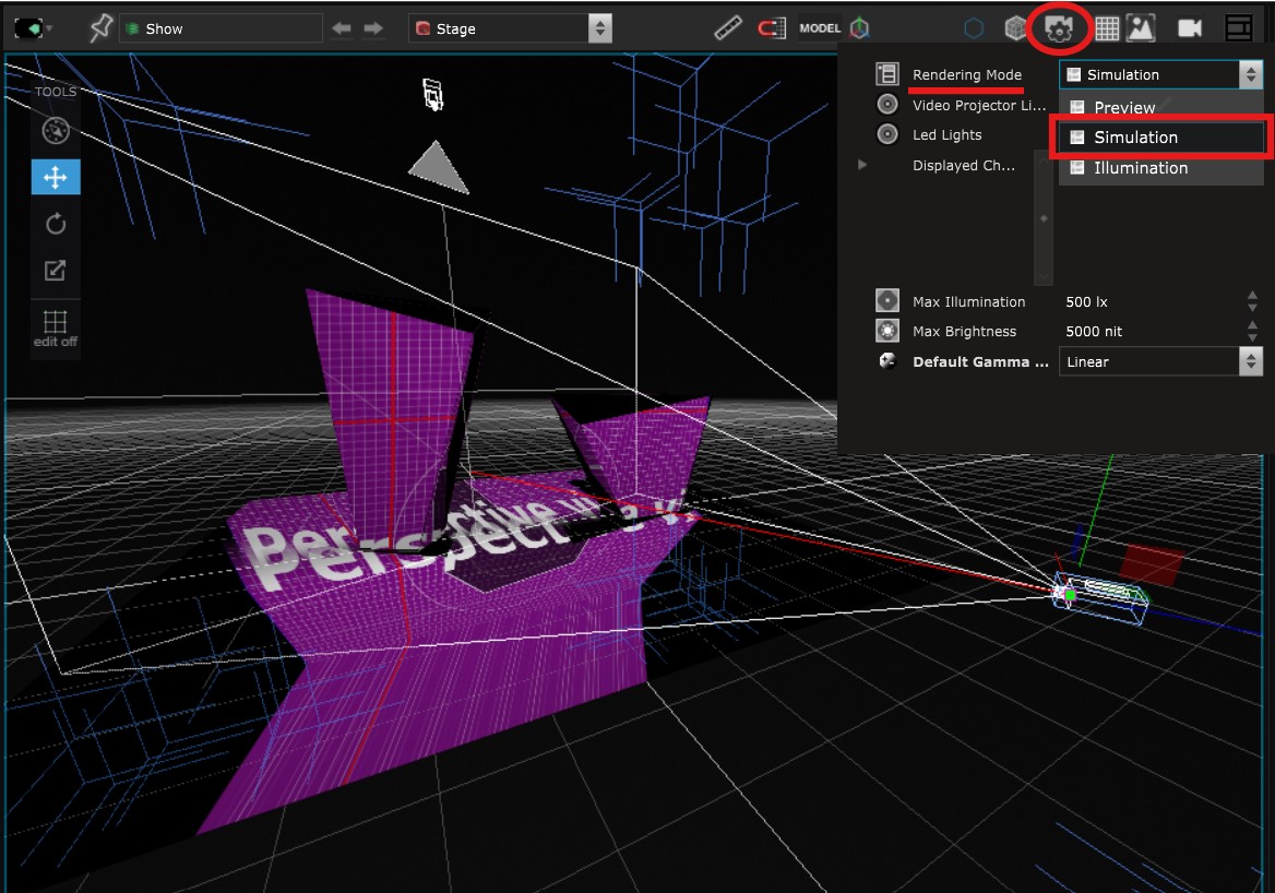
The simulation
 Viewport
is quite useful to see the pixel deformations of the
Video Projector
and also the soft edges and overlap issues:
Viewport
is quite useful to see the pixel deformations of the
Video Projector
and also the soft edges and overlap issues:
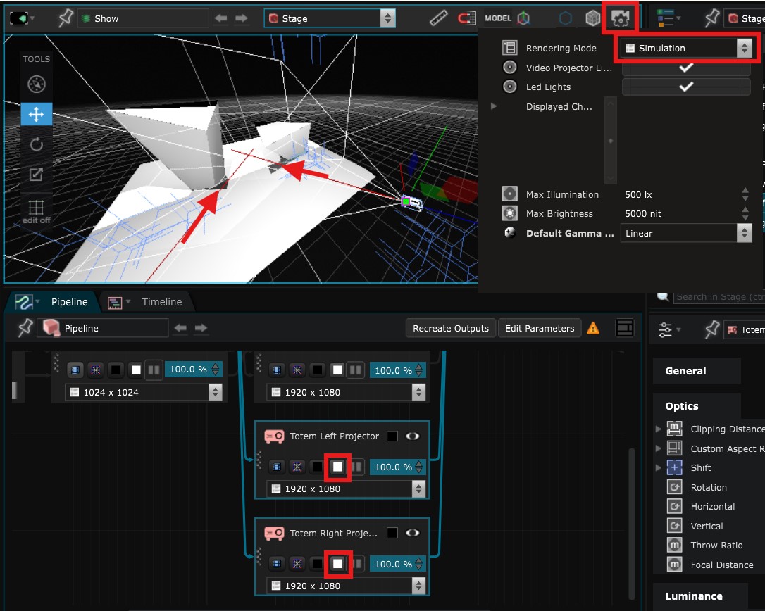
To have a more thorough simulation, you can send the full white mode from every video projector:
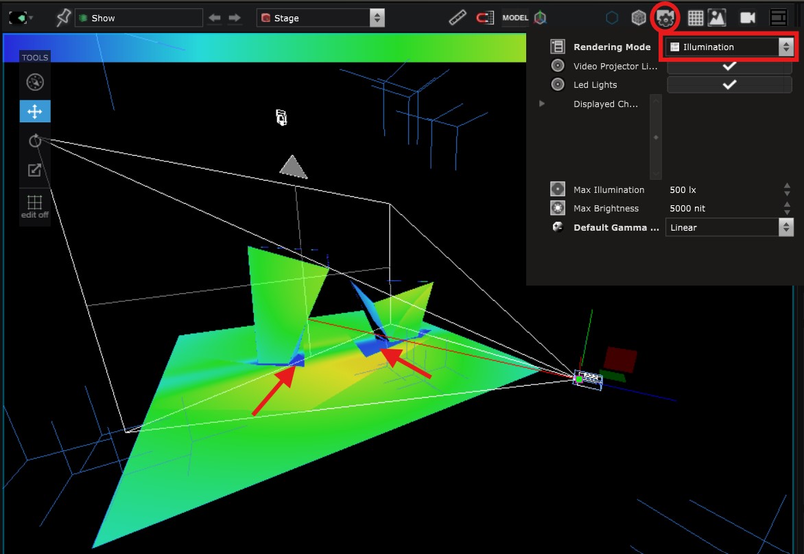
Or you can activate the illumination mode into the rendering options of the
Viewport
. This will not allow you see the soft edges but will be the most accurate way to do an illumination simulation :
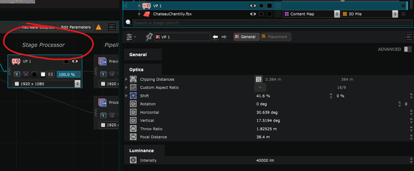
Understanding internal
Processor
In Smode, there are 2 types of
Processor
:
- Stage
Processor
are internal processors inside of video devices such as
Video Projector
or
Led Screen
.
They are created directly in the
Stage
inside the virtual devices. In these internal processors you will choose the content you want to send to your
Video Output Device
. - Pipeline
Processor
are rather working tools during the creation phase of the project.
They are created directly in the Pipeline Editor
by right click > Create > Processor, or in the
Pipeline Editor
by right click > Create > Processor, or in the
 Element Tree
in the
Element Tree
in the
 Pipeline
part.
Pipeline
part.
Learn more about the
Stage
by reading:
Create a stage pre-visualization
.
Create Soft Edges
Create Soft Edges for a video projector Output
Relight on a mapped object with 3D simulation
Quick Video Tutorial
Create a custom shape LED screen
How to create a round (or other shape) screen with LED pitch simulation
Create a Multi Video projectors dome with a Vioso calibration
Build a 6 Video-projectors dome setup with Vioso calibration file (www.vioso.com)
Create a full 3D mapping project from scratch
Quick Video Tutorial
Import as Group in the Stage
Learn how to name your object in the 3d Software of your choice before importing your FBX in Smode
Import CSV as Fixture
how to import a .csv file into a Stage to create your Led fixture
Create and import 3D files into LED Fixtures
Design your own LED structure
Use Posital values into Smode
The good process for using Posital values in Smode
Configure Network for posital
Configure the network for Posital sensors